Views: 0 Author: Site Editor Publish Time: 2026-10-08 Origin: Site


Modern electronics rely heavily on relays to bridge the gap between delicate low-power control logic and demanding high-power physical loads. Yet, hardware engineers sometimes gloss over the exact requirements of the coil driving mechanism. They might pick a component based on a quick glance at face-value specifications. Unfortunately, incorrectly specifying relay coil parameters leads to intermittent circuit failures, contact welding, or premature coil burnout. Relying purely on the nominal rating printed on the plastic casing ignores real-world variables. Thermal shifts and inherent drive circuit voltage drops frequently occur in production environments. This oversight severely compromises overall system reliability.
To achieve true stability, you must move beyond these surface-level ratings. You must deeply analyze datasheet limits for reliable system integration. This guide focuses entirely on evaluating coil voltage parameters. Our goal is to ensure accurate component selection. We will explore how to match these specifications for both delicate logic-level control and robust load switching.
Component selection happens during a critical decision stage. Engineers must evaluate what the technical specifications actually mean for circuit reliability. Looking at a datasheet reveals multiple voltage ratings. Each rating tells a specific story about how the component behaves under stress.
Manufacturers designate an ideal operating voltage for every coil. You will typically see standard values like 5V, 12V, or 24V. Engineers use this nominal value as the primary sorting metric for component shortlisting. However, it only represents an ideal laboratory baseline. Real-world power supplies fluctuate continuously. Therefore, treating the nominal value as a strict limit invites failure. You must look deeper into the specification table.
Pick-up voltage represents the guaranteed minimum voltage required to actuate the contacts. The magnetic field must overcome internal spring tension. This threshold guarantees actuation. Usually, manufacturers set this limit at 75-80% of the nominal voltage. When you evaluate the relay coil voltage, consider your drive circuit capability. The drive circuit must consistently deliver this minimum voltage. It must do so even under the worst-case voltage drop conditions. If your system voltage dips heavily under load, the relay will fail to switch.
Drop-out voltage dictates when the component reverts to its unpowered state. The magnetic field weakens as voltage decreases. Eventually, the spring forces the contacts apart. For DC coils, this threshold typically sits around 5-10% of the nominal rating. Solid-state drivers sometimes leak a small residual current. If the leakage exceeds the drop-out threshold, the contacts remain latched. You must verify that your driver fully cuts power below this critical percentage.
Every coil has an absolute upper electrical limit. Exceeding this boundary degrades the internal insulation. High voltage generates excessive heat within the windings. Thermal failure occurs quickly when you push past this limit. Most datasheets specify this maximum limit as 110-130% of the nominal value. Always verify the maximum allowable voltage if your power supply experiences sudden spikes.
Table 1: Relay Coil Parameter Reference Summary
| Parameter | Typical Range | Primary Function | Engineering Risk if Ignored |
|---|---|---|---|
| Nominal Voltage | Standardized (e.g., 5V, 12V) | Initial shortlisting and categorization | Falsely assuming perfect power supply conditions |
| Pick-Up Voltage | 75% - 80% of Nominal | Guarantees contact closure | Failure to actuate during supply voltage dips |
| Drop-Out Voltage | 5% - 10% of Nominal (DC) | Guarantees contact release | Contacts stay latched due to driver leakage current |
| Max Allowable Voltage | 110% - 130% of Nominal | Prevents thermal destruction | Coil burnout and insulation degradation |
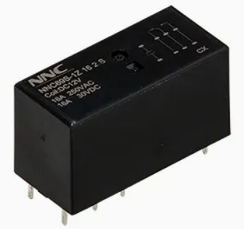
Engineers categorize solutions based on the physical and electrical environment. The demands of a logic board differ vastly from a factory floor. You must adjust your evaluation criteria accordingly.
Designing for printed circuit boards requires strict power management. Drive circuit constraints dictate the component choices. You will typically utilize 3.3V, 5V, or 12V coils. Microcontrollers drive these components via MOSFETs or transistor arrays. A standard PCB relay operates within very tight physical boundaries. It must perform flawlessly without draining the logic power supply.
Success criteria in this environment revolve around efficiency. You must balance low power consumption with sufficient magnetic flux. Sensitive coils draw less current from the board. However, they must still generate enough magnetic force to switch the required load. They must do this without overloading the logic board's power plane. Overloading the power plane causes microcontroller resets and erratic system behavior.
Industrial environments present a completely different set of challenges. Control loops stretch across long factory floors. Drive circuit constraints often force the use of 24V DC, 120V AC, or 240V AC. Higher voltages mitigate the effects of voltage drop over long wire runs.
Success criteria here focus on ruggedness and AC handling. AC coils operate differently than DC coils. The alternating current passes through zero volts twice per cycle. This zero-crossing causes the magnetic field to collapse momentarily. Manufacturers install copper shading rings inside AC models. These rings maintain the magnetic flux during zero-crossings. They effectively prevent the 50/60Hz humming sound. Furthermore, specifying must account for high inrush currents. These initial surges are typical of AC electromagnetic coils. A poorly sized driver will fail during the initial current spike.
Assessing operational risks ensures long-term reliability. When you ignore voltage boundaries, hardware fails. Understanding the exact failure modes helps you design better fail-safes.
Under-voltage is notoriously destructive. Applying a voltage slightly below the Pick-Up threshold results in a weak magnetic pull. The coil generates just enough force to move the armature. However, it lacks the power to hold the contacts firmly together. The internal spring fights back continuously.
The outcome is severe mechanical instability. The contacts bounce rapidly against each other. Engineers call this phenomenon contact chatter. Chatter leads to rapid electrical arcing across the tiny air gap. The localized temperature spikes dramatically. This extreme heat melts the contact material. The metals fuse together, causing contact welding. Ultimately, this results in catastrophic load failure.
Pushing too much voltage into the component presents a different danger. Operating continuously near or above the Maximum Allowable Voltage increases $I^2R$ losses. The copper windings convert the excess electrical energy into heat. The component cannot dissipate this thermal load fast enough.
The outcome is a steady degradation of internal materials. The insulation surrounding the copper wire breaks down. Once the insulation fails, adjacent wire turns short together. Shorted coil turns drastically drop the overall resistance. This pulls even more current, accelerating the thermal runaway. Eventually, the component suffers a reduced mechanical lifespan or outright burns up.
Ambient heat completely alters electrical properties. Inside any standard electromagnetic relay, copper coil resistance increases by approximately 0.4% per degree Celsius. As the enclosure heats up, the internal resistance climbs. A higher resistance means the coil draws less current at the same voltage. Less current means a weaker magnetic field.
This creates a massive risk factor for enclosed systems. A component might operate perfectly at 20°C on the test bench. However, it may completely fail to pick up at 85°C in the field. If the supply voltage is not adequately buffered, the weak magnetic field cannot overcome the spring tension. You must always consult the thermal derating curves to prevent this hot-environment failure.
Table 2: Common Failure Modes and Root Causes
| Failure Symptom | Primary Root Cause | Underlying Physics |
|---|---|---|
| Contact Welding | Under-Voltage Drive | Weak magnetic force causes contact chatter and arcing. |
| Coil Burnout | Over-Voltage Drive | Excessive $I^2R$ heating destroys wire insulation. |
| Fails to Actuate When Hot | Temperature Dependency | Copper resistance rises, dropping current and magnetic flux. |
| Fails to Release (DC) | High Driver Leakage | Leakage current exceeds the defined Drop-Out threshold. |
Finalizing component selection requires step-by-step logic. You cannot afford to guess when building a Bill of Materials (BOM). Follow this systematic decision framework to ensure perfect operational matching.
By strictly following these four steps, you eliminate the majority of field failures. A structured approach guarantees hardware resilience.
Specifying relay coil voltage remains a delicate balance of mechanical physics and electrical limits. It requires much more than just matching numbers on a schematic. You must account for voltage drops, thermal shifts, and driver leakage. Neglecting these details invites contact chatter, thermal runaway, and unpredictable system behavior. You must always consult the manufacturer datasheets. Carefully review the thermal curves, minimum pick-up thresholds, and maximum allowable limits before finalizing your Bill of Materials.
Your recommended next action is clear. First, map out your worst-case power supply metrics. Next, request engineering samples from your trusted component manufacturer. Finally, bench-test the coil performance extensively. Expose the samples to the specific temperature and load conditions of your intended application. Real-world testing validates your datasheet analysis and secures your final design.
A: Technically, it might work at room temperature if 9V sits above the 75% Pick-Up threshold. However, it is highly unreliable. As ambient temperature rises, copper resistance increases, requiring more voltage to generate sufficient magnetic flux. A 9V supply leaves zero safety margin. We do not recommend this for any production environment.
A: The coil will act as a high impedance choke. Because AC current constantly alternates, the DC-designed magnetic field will collapse continuously. The component will fail to actuate properly. It will chatter aggressively, generate excessive heat, and potentially burn out its internal windings very quickly.
A: This is called inductive kickback. When you cut power to an electromagnetic relay coil, the magnetic field rapidly collapses. This collapsing field induces a massive, reverse-polarity high voltage spike. You must install a flyback diode in DC circuits to safely dissipate this energy and protect your driver transistor.
A: No. The coil voltage strictly controls the internal electromagnet. The contacts have a completely separate voltage and current rating designed for the external load. These two systems are electrically isolated from each other. They are only physically linked by the mechanical armature.

 注: 建议图片大小150px*50px


