Views: 0 Author: Site Editor Publish Time: 2026-09-23 Origin: Site


Component selection often hides unseen risks. You might specify a relay using top-line datasheet numbers. This common practice frequently leads to premature field failures. It can also cause unnecessary BOM cost bloat. Engineering teams face critical choices during the decision stage. Moving from a functional prototype to volume production changes everything. You must shift focus from theoretical specifications to real-world circuit behaviors. Real-world applications rarely match ideal laboratory conditions.
To ensure long-term reliability and compliance, engineering and procurement teams must dig deeper. You must evaluate how specific load characteristics operate in practice. These unique electrical behaviors drastically alter a component's effective switching capacity. Understanding these dynamic forces prevents catastrophic failures. It also optimizes your design for both performance and manufacturing feasibility. Read on to master the principles of robust component selection.
Engineers frequently fall into a common trap when reading specification sheets. Top-line amperage ratings represent ideal laboratory conditions. Component manufacturers almost exclusively test these limits using purely resistive loads. A purely resistive load possesses a Power Factor of 1.0. This means the current and voltage waveforms remain perfectly synchronized. Real applications almost never operate under these perfect conditions. Therefore, a headline specification acts only as a theoretical maximum.
Many design teams attempt to bypass this reality gap through over-specifying. They might arbitrarily double the required rating to create a supposed "safety margin." This approach introduces major drawbacks. It unnecessarily increases the physical board footprint. It also drives up coil power consumption, which generates excess heat. Ultimately, this arbitrary margin inflates the per-unit cost. Scaling this bloat across thousands of production units wastes significant budget.
Conversely, under-specifying creates disastrous field results. Ignoring specific load types introduces catastrophic failure modes. When contacts cannot handle the invisible stresses of a circuit, they degrade rapidly. Severe arcing melts the metal surfaces. Contact welding permanently fuses the circuit closed. Alternatively, repeated micro-arcing creates severe carbon buildup. This carbon creates high contact resistance, which subsequently overheats the relay and destroys the surrounding board.
Different circuit loads behave in fundamentally different ways. You must match the component to the electrical physics of the application. Breaking down your load type provides the clearest path to reliable component selection.
Resistive loads act as the foundational baseline for electrical switching. Common examples include standard space heaters and traditional non-LED lighting elements. In these applications, current and voltage remain perfectly in phase throughout the operational cycle.
Because the load lacks complex turn-on surges or turn-off kickbacks, evaluation remains straightforward. The datasheet’s baseline PCB relay contact rating can generally be applied. You only need standard, minimal safety margins. If a heater draws 8 amps, a 10-amp rated contact will perform reliably over its mechanical lifespan.
Inductive loads introduce significant electrical turbulence. Examples include electric motors, solenoids, power transformers, and refrigeration compressors. In these circuits, the current naturally lags behind the voltage.
You must focus primarily on the disruption phase. When the relay attempts to open the circuit, the collapsing magnetic field releases stored energy. This generates a massive back Electromotive Force (EMF). This EMF causes severe electrical arcing across the opening contacts. The plasma arc literally vaporizes microscopic layers of metal. To survive this, you must derate the baseline specification by 30% to 50%, depending heavily on the measured power factor.
Capacitive loads stress the component at the exact opposite moment of the cycle. Examples include switching power supplies, LED lighting drivers, and motor start capacitors. These devices act like empty electrical reservoirs when first powered on.
This creates massive inrush currents at turn-on. An LED driver might pull a steady-state current of just 2 amps. However, its initial inrush can hit 40 amps for a few milliseconds. This extreme current melts the contact surfaces upon closure, creating a permanent weld. For capacitive circuits, you must focus heavily on the relay's maximum make/inrush rating. The continuous thermal current limit matters far less.
Table 1: Load Type Characteristics and Design Impacts
| Load Type | Common Examples | Primary Risk Factor | Key Selection Metric |
|---|---|---|---|
| Resistive | Heaters, Incandescent Lamps | Thermal limits at steady-state | Continuous Current Rating |
| Inductive | Motors, Solenoids, Transformers | Back EMF causing severe arcing | Break/Disconnect Rating |
| Capacitive | LED Drivers, Power Supplies | Massive turn-on inrush current | Make/Inrush Rating |
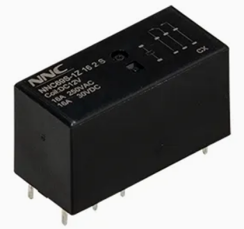
Electrical physics dictates that no single contact metal works for every application. Manufacturers utilize advanced metallurgy to counteract specific failure modes. You must align the contact chemistry with your load profile.
Engineers often mistakenly believe a high-power rating guarantees low-power performance. Standard power relays fail miserably at switching very low-level signals, often called dry circuits. Power contacts rely on a minimum electrical arc to burn off natural surface oxidation. Without this minimum voltage and current, the oxidation layer acts as an insulator. The circuit will show infinite resistance despite physical closure. For micro-loads, you must specify gold-clad signal contacts instead.
Electrical specifications represent only half of the selection process. The physical environment heavily influences component survival. Manufacturing workflows and operational climates dictate your enclosure choices.
Consider your manufacturing constraints. Modern PCB assembly often involves automated wave soldering followed by aggressive chemical washing. If your board undergoes this process, a fully sealed PCB relay becomes a strict requirement. Unsealed variants will allow liquid flux and cleaning agents to ingress. Once flux coats the internal contacts, the relay will fail immediately upon deployment.
However, sealing introduces thermal dissipation challenges. A sealed enclosure entirely restricts internal airflow. When switching heavy currents, the internal contacts generate significant heat. If you operate the device continuously at its maximum rating inside a high-ambient-temperature enclosure, it will overheat. You must perform careful thermal evaluations to ensure the plastic housing will not warp or melt.
To balance these factors, engineers utilize venting protocols. Many wash-tight components feature a small plastic nib on the top casing. After the wave soldering and chemical washing stages complete, technicians break this nib off. This simple action opens the enclosure to the surrounding air. It allows the off-gassing of ozone and carbon generated during everyday electrical arcing. Venting these corrosive gases drastically extends the mechanical and electrical life of the component.
Moving from theory to a finalized bill of materials requires a structured approach. Guesswork leaves your design vulnerable to unpredictable field failures. Follow a systematic benchmarking logic to isolate the perfect component.
Evaluating a switching component goes far beyond reading a single datasheet number. It remains an exercise in matching complex load realities to strict metallurgical limits. The inrush, steady-state, and break phases each apply different destructive forces to your contacts.
Before finalizing your bill of materials, your engineering teams should take immediate action. First, pull in-circuit oscillograms of your specific load transitions to reveal hidden transient spikes. Next, verify your exact environmental and manufacturing requirements to choose the correct enclosure type. Finally, consult directly with component manufacturers to request lifecycle curve data specific to your measured power factor. Taking these proactive steps ensures your product delivers flawless longevity in the field.
A: AC voltage naturally crosses zero volts during its cycle. This zero-crossing naturally extinguishes electrical arcs. DC voltage, however, remains constant. This means DC arcs sustain much longer and burn significantly hotter. Therefore, you need drastically lower current ratings for DC switching to prevent immediate contact destruction.
A: TV ratings (like TV-5 or TV-8) are specific UL testing standards. They indicate the component has been rigorously tested to withstand massive capacitive inrush currents. These surges are characteristic of turning on tungsten lamps or heavy power supplies. A TV rating proves the component possesses excellent anti-welding capabilities.
A: Generally, no. High-power contacts rely on a minimum voltage and current (known as wetting current) to burn off microscopic oxidation layers. Switching micro-loads with power contacts fails to break this oxidation. This leads to infinite resistance and signal failure. You must use gold-clad signal relays instead.

 注: 建议图片大小150px*50px


