Views: 123 Author: Site Editor Publish Time: 2026-10-15 Origin: Site


Undersizing a relay risks catastrophic thermal failure across your system design. Conversely, oversizing wastes valuable PCB real estate and dramatically inflates initial material costs. Engineers face a constant dilemma balancing these physical constraints against strict budget limits. Modern hardware applications demand precise load matching. Electric vehicle charging stations, battery energy storage systems, and solar inverters cannot rely on generic rules of thumb. You need accurate data to guarantee long-term system reliability.
This guide provides a robust framework for engineering and procurement teams. We will help you align complex system requirements with exact component capacities. You will learn how to verify safety ratings and secure essential regulatory compliance. By mastering these specification strategies, you will achieve maximum design efficiency and eliminate unnecessary production friction.
Selecting the right capacity requires calculating both continuous operational current and maximum fault/inrush current.
Insulation class and compliance certifications (UL, RoHS) are as critical as amperage ratings for preventing long-term liability.
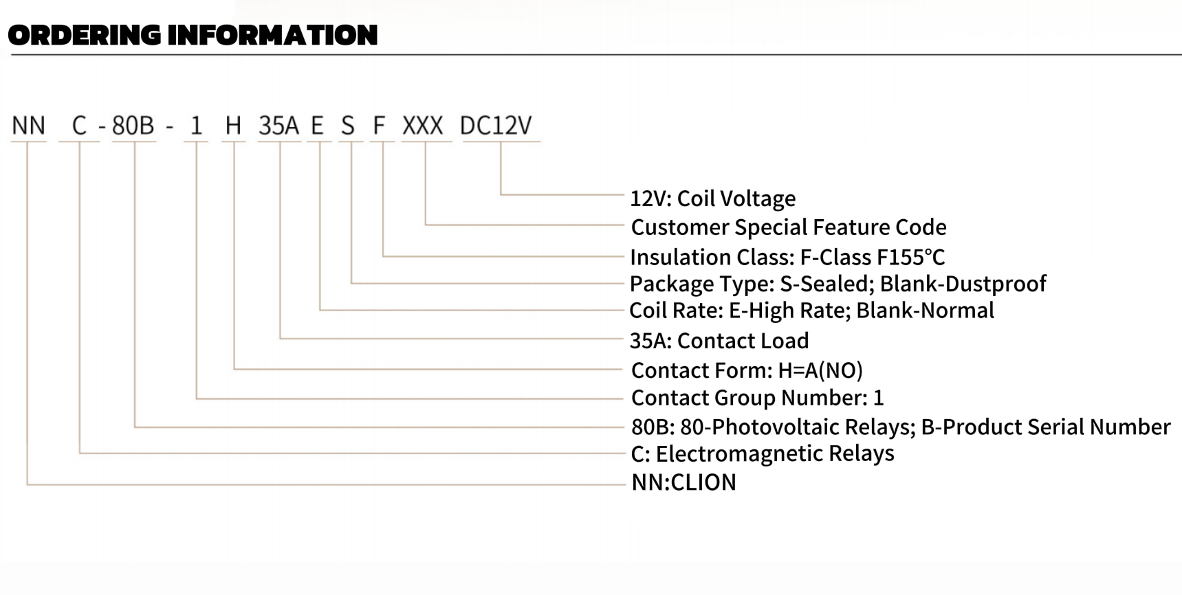
Specific project tiers (like Level 2 EV chargers) often align with standard profiles (e.g., 35A units with high thermal tolerance).
Partnering with an integrated new energy relay supplier reduces supply chain risk and ensures access to essential EOL (End-of-Line) testing data.
Start by differentiating your continuous load from your peak load. A steady-state carrying capacity dictates how the component handles normal, daily operation. However, every switching component must also break peak or inrush currents safely. If your design cannot handle these sudden electrical spikes, you risk severe contact welding. Welding creates immediate safety hazards because it prevents the circuit from opening during an emergency.
Next, carefully evaluate direct current (DC) versus alternating current (AC) loads. Direct current switching presents unique physics challenges. AC loads cross a zero-voltage threshold naturally dozens of times per second. This zero-crossing breaks electrical arcs automatically. DC arcs sustain themselves continuously. Therefore, a robust new energy relay must implement magnetic blowouts. These specialized structures force the arc outward, extinguishing it rapidly before it damages the internal contacts.
System voltage parameters dictate your baseline insulation needs. Higher maximum operating voltages require greater dielectric strength. Dielectric strength determines how much voltage the insulation can withstand before breaking down. You must also calculate appropriate clearance and creepage distances. Clearance represents the shortest path through the air between two conductors. Creepage represents the shortest path along an insulating surface. Industry standards dictate specific distances based on expected voltage spikes. Always verify these parameters before finalizing your PCB footprint.
Contact resistance remains a critical metric for thermal management. Lower contact resistance actively prevents excessive heat generation. As electrical current flows through closed contacts, any physical resistance creates thermal energy. This localized heat directly impacts component spacing on your circuit board. If you select components featuring low contact resistance (often measured in single-digit milliohms), you can safely pack devices closer together. Silver tin oxide (AgSnO2) contacts provide excellent resistance characteristics.
You must evaluate endurance ratings based on realistic deployment conditions. Evaluate new energy relay specifications by analyzing expected lifecycle data. Mechanical endurance measures lifespan without any active electrical load. Electrical endurance measures survival under full operating currents. The electrical lifespan is always significantly shorter than the mechanical lifespan. We advise buyers to request specific lifecycle test reports. Ensure these tests reflect your exact inductive or capacitive load types.
Coil power consumption severely affects your overall thermal budget. Maintaining a holding current generates steady heat over long durations. This constant draw lowers overall system efficiency. Latching mechanisms offer a smart alternative for many projects. They require electrical power only during state changes. Once latched, they maintain their position without consuming additional power. Non-latching designs draw continuous power to stay closed. Evaluate your application carefully. Latching components often provide a vastly superior thermal profile for energy storage enclosures.
Standardized capacity profiles simplify the procurement process significantly. A 35-ampere capacity fits several popular commercial applications perfectly. You will find this rating ideal for 7kW to 11kW residential EV chargers. It also suits mid-string solar inverters and auxiliary battery energy storage modules. Matching these common applications reduces the need for expensive custom engineering. Using proven profiles guarantees predictable performance in the field.
Thermal management requires proper material insulation. Class F insulation guarantees safe continuous operation up to 155°C. This specific temperature threshold is mandatory for enclosed environments. Tightly packed electronics enclosures trap ambient heat rapidly. Class F materials utilize advanced polyester resins. These materials prevent coil degradation under harsh thermal conditions. Class B insulation only survives up to 130°C. This lower rating often leads to premature failure in modern energy applications.
Compliance forms your baseline for product safety and market entry. Explicitly sourcing a 35a ul f class rohs new energy component minimizes friction during final product certification. Underwriters Laboratories (UL) certification covers rigorous North American safety standards. Restriction of Hazardous Substances (RoHS) compliance satisfies strict European environmental regulations. Specifying fully compliant parts early saves months of costly redesign time later.
Insulation Class Temperature Ratings Comparison
Insulation Class | Maximum Operating Temperature | Typical Application Environment | Risk of Thermal Degradation |
|---|---|---|---|
Class A | 105°C | Basic consumer electronics | High in enclosed power systems |
Class B | 130°C | Standard industrial controls | Moderate during peak loads |
Class F | 155°C | EV chargers, BESS, Solar | Low under sustained operations |
Class H | 180°C | Extreme aerospace/military | Minimal but often cost-prohibitive |
PCB integration presents substantial physical layout challenges. You must analyze the physical footprint alongside the terminal layout. Thick copper traces require careful routing techniques. If you fail to optimize trace widths, you risk severe thermal throttling. Follow IPC-2221 standards strictly for current-carrying trace calculations. Poor solder joints also limit maximum current capacity. Ensure your wave soldering profiles match the component manufacturer recommendations perfectly.
Environmental stressors reduce component lifespans rapidly. Electric vehicle applications introduce constant physical vibration. Outdoor solar arrays face high humidity and persistent dust ingress. We highly recommend evaluating sealed or flux-free configurations. Fully sealed plastic enclosures protect internal metallic contacts from atmospheric contamination. This protection prevents oxidation and maintains low contact resistance.
Follow these critical steps to optimize your PCB integration:
Verify all trace width calculations against expected peak fault currents.
Select fully sealed enclosure ratings (like IP67) for outdoor hardware installations.
Perform comprehensive thermal imaging during your initial prototype testing phase.
Design optimal copper pour areas around terminals for maximum heat dissipation.
Implement mechanical vibration dampening for vehicle-mounted applications.
Avoid over-specification at all costs. Simply buying the largest available component represents a deeply flawed strategy. Larger components contain heavier armatures. This increased mass demands significantly higher coil draw. Larger mass also dictates much slower actuation times. Slower break times increase arcing duration. Furthermore, oversized parts add unnecessary cost to your BOM. Match the capacity tightly to your validated engineering requirements.
Manufacturing traceability defines a credible manufacturing partner. A qualified new energy relay supplier must provide transparent documentation for every shipment. Demand comprehensive End of Line (EOL) test reports for every batch. Ask for X-ray inspection data confirming precise internal physical alignments. Granular batch traceability ensures you can isolate and resolve field issues quickly. Lack of traceability introduces unacceptable liability into your supply chain.
Consider the benefits of customization versus off-the-shelf options. Standard components offer significantly faster lead times. They also provide highly predictable baseline performance. However, you might require custom coil voltages for specific logic boards. Unique terminal configurations also require custom tooling. Weigh the long-term engineering benefits against extended initial lead times. High-quality partners offer rapid prototyping for custom terminal designs.
Evaluate overall supply chain resilience carefully. Assess the manufacturer's total production capacity. Investigate their lead time stability during previous global market fluctuations. They must handle scaling production volumes easily as your product gains market share. Ask about their secondary sourcing for raw materials like copper and silver. A resilient manufacturing partner prevents catastrophic line stoppages at your final assembly plant.
Optimal capacity selection demands a careful engineering balance. You must weigh electrical specifications against thermal management limits. Strict regulatory compliance remains entirely non-negotiable for modern projects. Precision ensures reliable long-term performance across demanding environments.
Calculate precise inrush currents rather than relying on standard carrying capacity alone.
Mandate Class F insulation to prevent catastrophic thermal failure inside sealed enclosures.
Refuse to over-specify; larger components draw more power and actuate slower.
Demand complete batch traceability and EOL reporting from your manufacturing partners.
We encourage technical buyers to audit peak load requirements immediately. Request detailed specification sheets from shortlisted suppliers. Order engineering samples today to begin physical validation. Proactive testing now prevents catastrophic field failures tomorrow.
A: Apply standard engineering margins of 20-25% above your continuous load requirement. This margin accounts for unexpected thermal dissipation limits within tight enclosures. Overestimating beyond 25% wastes space and increases coil power consumption unnecessarily.
A: Class F insulation safely withstands continuous operating temperatures up to 155°C. Class B maxes out at 130°C. Tightly enclosed electronics in solar and EV applications frequently exceed 130°C. Class F ensures reliable performance without premature resin degradation.
A: A closed-failure creates severe safety risks. It allows uncontrolled power back-feeding into the grid or damaged components. You must use specialized relays featuring magnetic blowouts and anti-welding contact materials to prevent this catastrophic fault.
A: No. Standard industrial relays lack specialized DC arc-blowout structures. They also frequently lack the specific high-voltage compliance ratings required for modern energy grids. Using standard components in these high-stress environments virtually guarantees premature field failure.

 注: 建议图片大小150px*50px


