Views: 0 Author: Site Editor Publish Time: 2026-10-11 Origin: Site


Picture this. You are finalizing a control panel design. You stare at the wiring schematic and hit a familiar roadblock. Which switching component should actually make the final cut? Choosing between mechanical and solid-state switches often feels like navigating an engineering minefield. Make the wrong call here. You might face catastrophic circuit failures, erratic machine behavior, or bloated manufacturing budgets.
As an engineer who has spent years designing industrial water pump controls and heavy-duty motor starters, I know this struggle firsthand. Relays act as essential gatekeepers. They allow a low-power digital signal to safely command a high-power industrial load. Yet, the internal mechanisms they use to achieve this are worlds apart. In this comprehensive guide, we will break down the exact differences between traditional mechanical switches and modern semiconductor alternatives. This will help you pick the perfect component for your specific electrical ecosystem.
No Moving Parts: Solid State Relays, commonly referred to as SSRs, utilize semiconductor materials for switching. This structural design makes them completely silent and immune to mechanical friction. Normal relays rely on physical moving contacts that wear down over time.
Speed and Lifespan: SSRs actuate in mere microseconds. They offer a virtually infinite operational lifespan under proper conditions. Conversely, mechanical variants actuate much slower and degrade steadily due to contact arcing.
Thermal Management: Semiconductor devices generate internal heat due to electrical resistance. They frequently require dedicated aluminum heat sinks. Normal relays run significantly cooler even under heavy electrical loads.
Cost vs. ROI: Traditional relays are remarkably cheaper upfront. However, SSRs consistently provide a superior long-term Return on Investment in high-frequency, continuous-duty applications by eliminating maintenance downtime.
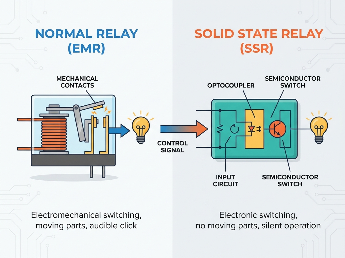
To make an informed engineering decision, we must first understand the traditional baseline. A normal relay, technically classified as an electromechanical relay, is a classic electrical switch operated by an electromagnet. It allows a low-voltage control signal, such as a 5V output from a basic microcontroller, to safely engage a 240V AC motor. All the while, it maintains strict electrical isolation between the two circuits.
This component relies on tangible, physical mechanics. Crack open the plastic casing of a standard industrial relay. You will find four primary structures. These include a copper electromagnetic coil, a movable metal armature, a tensioned return spring, and a set of physical electrical contacts.
When voltage hits the input terminals, current floods the coil. This instantly generates a concentrated magnetic field. This invisible force physically yanks the metal armature toward the coil, fighting the resistance of the return spring. As the armature snaps into place, it forces the electrical contacts to smash together, bridging the high-power circuit. Cut the control voltage, and the magnetic field vanishes. The spring then violently pulls the contacts apart. This breaks the circuit with a distinct, audible click.
Because of their rugged nature and high tolerance for sudden electrical faults, electromechanical relays have dominated the industry for decades. You will find them heavily utilized in automotive fuse boxes, legacy HVAC control boards, and heavy industrial motor starters. In these environments, massive inrush currents are simply a part of daily operation.
As modern electronic control systems evolved to become faster and far more precise, the physical limitations of traditional mechanical switches became a severe bottleneck. Solid State Relays emerged as the modern electronic solution. They perform the exact same core function. They turn a high-power circuit on and off via a small external voltage. However, they do so without a single moving part.
The defining characteristic of an SSR is the complete absence of magnetic coils, springs, or clashing metal. Instead of utilizing magnetic kinetic energy, SSRs rely on optical isolation, known as optocouplers, and advanced silicon engineering.
Specifically, when you apply a control signal to an SSR, it powers a microscopic internal Light Emitting Diode. This LED shoots a concentrated beam of light across a tiny internal void. It strikes a photo-sensitive semiconductor on the load side. This light instantly triggers the semiconductor to change its state from an insulator to a conductor. This allows the heavy current to flow. Photons of light are the only things bridging the gap. Therefore, the sensitive low-voltage control side remains entirely isolated from the dangerous high-voltage load side.
Depending on the specific nature of the current being controlled, SSRs utilize different semiconductor materials to execute the heavy lifting. Thyristors and TRIACs are primarily deployed for switching Alternating Current loads. Metal-Oxide-Semiconductor Field-Effect Transistors, commonly called MOSFETs, are the go-to choice for Direct Current applications due to their exceptionally low on-state resistance.
Looking at the broader industrial automation landscape, recent engineering analyses highlight a definitive market pivot toward semiconductor-based switching. Driven by the rapid expansion of EV charging infrastructure, high-density smart grids, and precision manufacturing, engineers are increasingly prioritizing compact, maintenance-free components. The demand for flawless, high-frequency thermal regulation in semiconductor manufacturing and automated packaging is pushing SSR adoption to record highs.
However, traditional electromechanical relays are not vanishing. They are evolving into specialized niches. Market analysis shows a sustained, robust demand for mechanical contactors in renewable energy sectors, specifically solar inverters and battery storage systems. In these applications, strict international safety regulations mandate the absolute galvanic isolation that only a physical air gap can provide. Ultimately, the industry is moving toward a hybrid approach. System architects now leverage the speed of silicon for control logic and the ruggedness of mechanical contacts for primary safety disconnects.
Choosing between an SSR and an electromechanical relay fundamentally alters the thermal profile, physical footprint, and longevity of your electrical panel. Let us break down how these two technologies clash on the engineering floor.
Feature | Solid State Relay | Normal Electromechanical Relay |
|---|---|---|
Switching Mechanism | Semiconductors and optical isolation | Electromagnetic coil and physical contacts |
Operating Speed | Instantaneous, typically under 1 millisecond | Slower, typically 5 to 15 milliseconds |
Lifespan | Virtually infinite if properly cooled | Finite, usually 100,000 to 1,000,000 cycles |
Acoustic Noise | Completely silent | Audible clicking sound |
Heat Generation | High, requires dedicated heat sinks | Low, runs cool under normal loads |
Leakage Current | Present, allows a microscopic trickle of power | Zero, provides a true physical air gap |
The most profound distinction lies in how they actually move electricity. Normal relays rely on kinetic energy, literally slamming metal against metal. Over months and years, this mechanical violence causes internal hinges to fatigue and contacts to deform. Solid State Relays operate entirely at the atomic level. Because nothing physically moves, there is zero physical wear and tear. This makes them exceptionally reliable in environments plagued by constant machine vibration.
When a mechanical relay closes, the physical contacts do not simply touch and stop. They bounce against each other microscopically for several milliseconds before finally settling. This phenomenon, known as contact bounce, sends rapid, unintended electrical pulses down the line. While a warehouse lightbulb will not notice this dirty signal, a sensitive digital PLC will register these bounces as multiple distinct commands. This often triggers software crashes.
Semiconductors eliminate this headache entirely. The transition from off to on is instantaneous, surgically clean, and occurs in fractions of a millisecond. This pristine signal integrity is vital for modern microcontrollers.
Despite their futuristic appeal, semiconductors have two distinct engineering vulnerabilities. First, they are not perfect conductors. They exhibit internal resistance, causing a slight voltage drop across the relay. At high amperages, this resistance generates serious heat. If a technician forgets to apply thermal paste and mount the relay to an aluminum heat sink, the SSR will literally cook itself to death. Mechanical relays, utilizing solid copper and silver contacts, exhibit near-zero resistance and run incredibly cool.
Second, SSRs suffer from leakage current. Even when the relay is commanded to turn off, a microscopic trickle of electricity still bleeds through the silicon. This leakage mandates strict safety protocols during routine machine maintenance. Normal relays, by contrast, provide a true physical air gap with infinite resistance.
To move from abstract theory to practical application, let us look at real-world specifications. When sourcing components from established manufacturers like NNC Relay, the performance metrics become crystal clear.
For high-frequency industrial heating, an industrial solid state relay might handle load currents ranging from 10A up to 120A, with a control voltage of 3 to 32V DC. These units boast a dielectric strength of over 2500V AC. This ensures that even without a physical air gap, the control circuitry remains fiercely protected from high-voltage load surges.
In contrast, consider a standard electromechanical power relay designed for heavy motor loads. These units typically feature silver alloy contacts capable of seamlessly handling massive 40A to 80A inrush currents. The physical contact resistance is often less than 50 milliohms. This incredibly low resistance explains exactly why mechanical relays do not require bulky heat sinks, even when switching heavy industrial water pumps.
Selecting the correct switching component is rarely a simple matter of matching voltage and current ratings. System designers must evaluate a complex matrix of operational demands, environmental conditions, and long-term maintenance logistics. Here is a practical, standardized framework to guide your decision.
The most critical deciding factor is the required cycle rate. Does your system require continuous, rapid cycling? If so, an SSR is mandatory. For instance, PID temperature controllers regulating industrial ovens, plastic injection molding machines, or 3D printer heated beds rely on rapid pulsing to maintain exact heat levels. A mechanical relay would literally beat itself to death in weeks under these conditions.
In addition, they are the only choice for acoustically sensitive environments. In hospital ICUs or high-end home theaters, the constant clicking of mechanical relays is unacceptable. Finally, if you are wiring mobile robotics, the epoxy-encapsulated solid-state components will completely ignore extreme external vibrations. Such vibrations would otherwise cause mechanical contacts to accidentally bounce open.
If your application only requires a circuit to be turned on once a day, the cost premium of an SSR is entirely unjustified. For basic water pump controls, standby power circuits, or budget-constrained projects, traditional electromechanical relays remain the logical, economical choice.
Furthermore, mechanical contacts are exceptionally robust when handling sudden electrical anomalies. Large AC motors draw massive inrush currents upon startup, often five to seven times their normal operating current. Mechanical relays can absorb these temporary thermal overloads without sustaining permanent damage. Lastly, in safety-critical isolation circuits where maintenance personnel work on high-voltage machinery downstream, the true air-gap of a normal relay is non-negotiable. It absolutely prevents lethal leakage current.
When procurement teams evaluate switching components, the immediate reaction is often to look strictly at the unit price. In a direct part-to-part comparison, electromechanical relays win effortlessly. A standard 10-amp normal relay might cost a mere fraction of its solid-state counterpart. An equivalent SSR, complete with the necessary external heat sink, requires a noticeably higher upfront budget.
However, professional engineering requires evaluating the Total Cost of Ownership. Let us look at a commercial packaging machine that pulses a heating element every three seconds. That equates to 28,800 cycles per day. A high-quality mechanical relay rated for one million cycles will reach its absolute end-of-life in just thirty-four days.
Every month, the machine must be powered down. A maintenance technician must spend thirty minutes replacing the degraded relay. If thirty minutes of halted production costs the facility hundreds of dollars in lost revenue, the true cost of using that cheap mechanical relay skyrockets annually. Conversely, an industrial-grade SSR installed in that exact same machine will easily handle the daily cycles for a decade without a single failure. In high-frequency applications, the solid-state upgrade is an undeniable financial necessity.
Yes, but a direct drop-in replacement requires careful engineering adjustments. You cannot simply swap the wires and walk away. First, you must account for heat dissipation. Mechanical relays run cool, but SSRs generate significant heat. They almost always require the addition of an external aluminum heat sink and thermal compound. Second, you must ensure the SSR matches your specific load type. Unlike mechanical contacts which pass both AC and DC indiscriminately, SSRs are highly specific. You must purchase an AC-switching SSR for AC loads, or a DC-switching SSR for DC loads. Using the wrong type will result in immediate failure.
Yes, heat generation is the primary operational disadvantage of semiconductor-based switching. This occurs due to internal electrical resistance, commonly referred to as voltage drop. When an SSR is conducting electricity, there is typically a 1-volt to 1.5-volt drop across the internal silicon terminals. If you are switching a 20-amp load, the relay will generate roughly 20 to 30 watts of pure thermal energy. If this heat is not rapidly drawn away by a heat sink, the internal silicon will exceed its maximum temperature rating and permanently melt.
This phenomenon is known as leakage current, and it is an inherent characteristic of all semiconductor devices. Unlike a mechanical relay that creates a physical air gap to break a circuit completely, an SSR relies on altering the electrical properties of silicon to block current. Even in its most restrictive off state, a microscopic amount of current, typically between 1mA and 10mA, will continue to leak through. While harmless to heavy industrial heating elements, this leakage can cause sensitive LED lights to flicker and poses a shock hazard during maintenance.
Normal relays, specifically heavy-duty versions known as contactors, are generally preferred for controlling large electric motors. Motors represent highly inductive loads that generate massive inrush currents when starting up. A motor running at 10 amps might briefly draw 60 amps the moment it is turned on. Mechanical contacts are physically robust enough to handle this temporary surge without damage. If you use a standard SSR, that same 60-amp surge can instantly vaporize the internal silicon junction, unless you purchase a massively oversized, highly expensive motor-rated SSR.
Testing an SSR requires a different approach than testing a mechanical relay. Because of internal leakage current, simply using a multimeter in continuity mode will often give false readings. The most reliable method is to connect a small load, like an incandescent light bulb, to the output terminals along with the appropriate power supply. Then, apply the rated control voltage to the input terminals. If the bulb turns on when control voltage is applied and turns completely off when removed, the SSR is functioning correctly. If the load stays on continuously or never turns on, the internal semiconductor has likely failed.
The absolute leading cause of SSR failure is thermal runaway due to inadequate heat dissipation. When an SSR operates, its internal resistance generates heat. If the relay is not properly mounted to an appropriately sized aluminum heat sink with thermal paste, the internal temperature will rapidly exceed the silicon's maximum threshold. This thermal stress causes the semiconductor junction to permanently short-circuit, meaning the relay will fail in the closed, or on, position. Voltage spikes and transient surges are the second most common cause of catastrophic failure.
Ultimately, choosing the right relay depends entirely on the specific heartbeat of your project. Solid state relays excel in high-speed, repetitive operations. They offer silent switching and incredible long-term durability that eliminates costly maintenance downtime. Normal relays, on the other hand, provide rugged, fault-tolerant performance for simple power isolation. They remain highly cost-effective for low-frequency applications.
Always evaluate your switching frequency, ambient temperature, and safety isolation requirements carefully before making a final decision. By matching the component's strengths to your system's demands, you ensure both operational safety and budget efficiency.
If you are still unsure which technology suits your control panel, or if you are ready to source industrial-grade switching components, explore the comprehensive catalog of relays at NNC Relay. Whether you need the infinite lifespan of an SSR or the brute-force reliability of an electromechanical contactor, NNC Relay provides the exact specifications your project demands. Reach out to their engineering specialists today for expert component selection.

 注: 建议图片大小150px*50px


