Views: 135 Author: Site Editor Publish Time: 2026-09-10 Origin: Site


A relay socket is never just a basic commodity. It serves as a critical point of failure in modern electrical control systems. Poor component quality often causes rapid thermal runaway, frustrating intermittent faults, and costly system downtime. Procurement and QA engineers face a tough dilemma today. They must constantly balance bulk component costs against the absolute need for long-term reliability. Accepting sub-standard components introduces unacceptable risks directly into your control panels.
We introduce a standardized acceptance framework below to help you validate quality thoroughly. You will learn how to ensure specification alignment and mitigate deployment risks before finalizing any bulk orders. Our guidelines establish strict incoming inspection rules. They empower your receiving teams to separate reliable hardware from dangerous knock-offs immediately.
Always cross-reference delivered batches against initial relay socket specifications for material composition and dimensional tolerances.
Mechanical retention force and DIN rail mounting stability are primary indicators of manufacturing consistency.
Electrical acceptance requires dielectric strength verification and contact resistance testing, even prior to relay insertion.
Vetting your relay socket supplier for stringent QA processes and industry certifications (UL, CE, RoHS) is as critical as testing the hardware.
Sub-standard components carry hidden dangers. You might waste countless hours diagnosing "ghost" intermittent faults. These elusive problems usually stem from poor terminal tension inside the plastic housing. High-resistance connections can easily spark severe fire hazards. We must define what a "passing" grade looks like for incoming component batches. Establish strict business problem framing immediately. You should highlight exactly how bad hardware damages overall system integrity.
Outcomes-focused evaluation requires shifting your mindset completely. You must enforce zero defect tolerance on all safety-critical components. We expect guaranteed lifecycle ratings based on empirical data. The unit must maintain stable thermal performance under maximum load. When you pull a random sample from a delivery, it must perform flawlessly. Tolerating minor defects creates massive vulnerabilities later.
Establish a firm baseline for risk mitigation today. Thorough acceptance testing is vastly cheaper than handling field replacements later. Field failures destroy customer trust quickly. A single melted terminal block causes severe reputational damage. We protect our brands through aggressive incoming quality control. You build robust systems only by verifying every foundational element first.
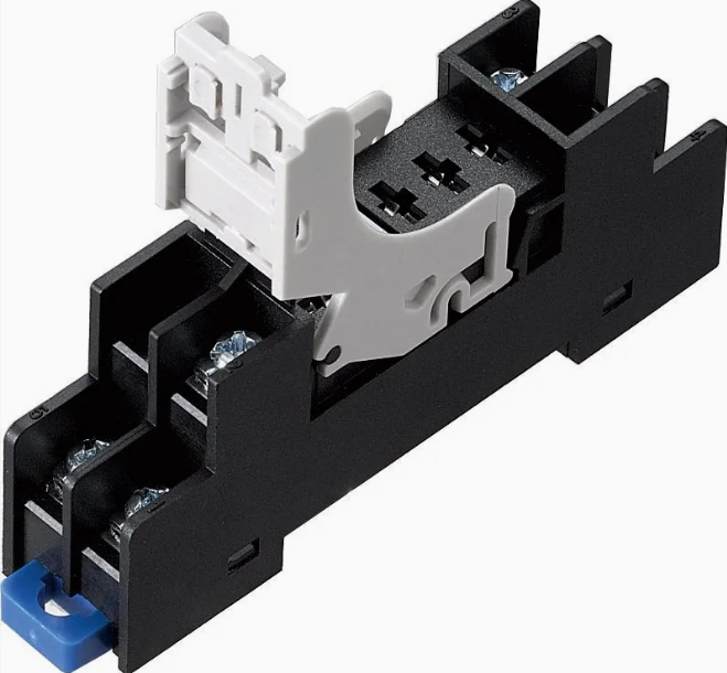
You must establish a strict protocol immediately upon receiving new inventory. Check delivered physical components directly against your original engineering schematics. Always reference your baseline datasheets to confirm precise dimensional accuracy. Do not assume previous batch dimensions apply automatically to current deliveries.
Material verification demands close attention from your QA team. Inspect insulating body materials for proper flame-retardant properties. They should strictly comply with UL94 V-0 safety standards. This rating ensures the plastic self-extinguishes within seconds after removing a flame source. Verify terminal material composition next. Look for robust copper alloys featuring adequate protective plating. Proper plating prevents rapid oxidation over time. Cheap brass alternatives degrade quickly in humid environments.
Finally, guarantee explicit application matching for every unit. The housing rating must explicitly match the continuous current requirements of your circuit. It must also handle the voltage demands of the intended load safely. Mismatches cause immediate overheating. A 10-amp load running through an 8-amp terminal creates dangerous thermal buildup. We verify these ratings physically before authorizing any installation procedures.
Pin and terminal integrity dictate the physical lifespan of your components. Check every batch carefully for bent, misaligned, or recessed contact pins. Test the insertion and extraction forces manually. The housing should grip the inserted unit firmly. It must not require excessive force. Excessive force easily damages delicate pins during routine maintenance. Follow these specific mechanical checks:
Visual Alignment Check: Inspect the pin cavities under good lighting. Ensure all metal contacts sit flush and parallel.
Insertion Force Test: Push a known-good relay into the base. You should feel a positive, tactile engagement.
Extraction Force Test: Pull the unit out. It should resist slightly but release without requiring aggressive wiggling.
Next, validate torque and wiring stability. Assess the thread quality of all terminal screws. Ensure they withstand the specified tightening torque easily. They must not strip or crack the plastic housing. Stripped threads ruin maintenance schedules entirely. Technicians rely on strong threads to secure heavy-gauge wires safely.
Test mounting mechanisms thoroughly across your samples. Clip them onto standard DIN rails. Verify panel mounting holes precisely. They need secure, vibration-resistant seating. Loose components rattle during machine operation. This vibration eventually severs wired connections. For industrial standards checks, benchmark your tests against known high-demand models. The nnc69k p69f05a1 industrial relay socket represents an excellent benchmark. Evaluate how well its heavy-duty locking mechanisms perform. Note how it resists industrial vibration seamlessly. You want your bulk orders matching this level of structural integrity.
Perform pre-installation multimeter checks first. Detail the exact process for testing continuity clearly. Identify any potential short circuits between adjacent terminals. You should isolate pins 30, 87, 85, and 86 carefully. Probing these connections ensures no internal metal bridges exist. A solid internal connection means reliable signal transfer.
Move onto contact resistance evaluation next. Measure the millivolt drop directly across the closed terminals. High resistance indicates poor internal connections. These weak connections generate dangerous heat under normal loads. We recommend using a four-wire Kelvin resistance measurement method. This approach eliminates test-lead resistance errors entirely. Clean metal surfaces yield minimal voltage drops.
Outline the necessity of Dielectric Withstanding Voltage (Hi-Pot) testing. You must verify actual insulation strength practically. Check between adjacent contacts and the main mounting surface. This ensures maximum safety under unpredictable voltage spikes. Weak plastics allow arcing during power surges. Arcing destroys sensitive microcontrollers downstream.
Test Type | Methodology | Acceptable Benchmark | Failure Implication |
|---|---|---|---|
Continuity Check | Digital Multimeter probe across internal/external pads | Solid tone / < 0.5 Ohms | Broken internal traces; dead on arrival |
Contact Resistance | Millivolt drop test under 1A load | < 50 milliohms | Severe thermal buildup during operation |
Dielectric Strength (Hi-Pot) | Apply 1000V AC between adjacent terminals for 1 minute | No arcing or breakdown | Vulnerability to voltage transients; fire risk |
Batch consistency matters immensely when handling large procurement volumes. We highly recommend using randomized sampling in all bulk orders. This detects manufacturing drift quickly. It also catches tooling wear at the factory level early. Factories occasionally swap materials without notifying buyers. Rigorous intake sampling prevents these unauthorized substitutions from entering your assembly line.
Compliance Authenticity: Verify certifications independently. Look for up-to-date IEC and ANSI/IEEE standards. Check the online databases for UL or CE marks. Do not accept expired documentation.
Traceability Logic: Assess the manufacturer's batch tracking system. You must know exactly when and where they produced a specific lot. Good traceability isolates defective runs quickly.
RMA and Warranty: Review their return merchandise authorization logic. Ask about their root-cause analysis reporting capabilities. Demand solid long-term warranty commitments.
A transparent partner eagerly shares their internal QA data. They provide detailed test reports alongside every shipment. Treat their documentation process as a major grading factor. Reliable hardware requires a reliable origin.
Molding flash and debris ruin connectivity fast. Inspect closely for excess plastic flash. It often hides deep inside terminal cavities. This microscopic plastic blocks electrical contact completely. Injection molding processes occasionally leave these artifacts behind. Your receiving team must spot them before assembly begins. Flash removal wastes valuable technician time later.
Watch for poor plating quality out of the box. Look for uneven plating surfaces. Spot early signs of oxidation immediately. Dull or discolored metal indicates poor chemical baths during manufacturing. We reject oxidized terminals instantly. They guarantee future resistance issues. High-quality terminals maintain a bright, consistent finish.
Spring fatigue is another major hidden issue. Test internal leaf springs thoroughly. They often lose tension after just a few repeated insertions. This particular flaw plagues low-tier components heavily. We recommend plugging and unplugging a test unit twenty times. The twentieth pull should feel just as tight as the first. Loose springs cause micro-arcing. Micro-arcing carbonizes the contacts. This cycle destroys the entire assembly rapidly.
Visible Defect | Immediate Symptom | Manufacturing Root Cause |
|---|---|---|
Excess Plastic Flash | Relay refuses to seat fully | Worn injection molds; poor factory QA |
Dull / Discolored Terminals | High contact resistance; overheating | Substandard electroplating chemical baths |
Stripped Screw Threads | Unable to secure wiring; loose wires | Low-grade metal alloys; incorrect tapping |
Loose Internal Springs | Intermittent circuit operation | Improper metal tempering; cheap materials |
Implement strict shortlisting logic immediately. Discard batches failing mechanical torque baselines without hesitation. Reject items failing electrical resistance checks instantly. Compromising on these baselines guarantees field failures later. We strongly advise establishing a standardized intake checklist for your receiving department. Equip them properly. Give them the right multi-meters and torque screwdrivers. Train them to recognize poor plating visually.
Maintain an ongoing, transparent feedback loop alongside your manufacturing partners. Share your internal testing data freely. This continuous communication ensures future batch consistency. Take action today. Update your procurement SOPs. Enforce these mechanical and electrical protocols rigorously. Your control systems will run significantly longer. Your diagnostic downtime will drop to zero. Uncompromising acceptance criteria remain your best defense against catastrophic electrical failures.
A: Set your multimeter to continuity or resistance mode. Probe the internal contact pads against their corresponding external screw terminals. You want to verify a solid internal connection. A reading close to zero ohms indicates a healthy trace. Any high resistance suggests internal breakage.
A: Thermal degradation stands out as the primary culprit. Loose terminal screws or poor internal spring tension cause this issue. They create high contact resistance. This resistance generates excessive heat, eventually melting the surrounding plastic housing completely.
A: Yes, the fundamental voltage and continuity principles remain identical. However, industrial versions require much stricter dielectric and torque validation. Industrial environments feature significantly higher voltages and continuous duty cycles. They demand greater physical robustness than standard 12V automotive applications.

 注: 建议图片大小150px*50px


