Views: 0 Author: Site Editor Publish Time: 2026-09-26 Origin: Site


Unplanned downtime wreaks havoc on industrial systems. A single relay failure often triggers costly system troubleshooting. It forces you into sudden, reactive equipment replacement. We must acknowledge a harsh engineering reality up front. Because they are electromechanical devices, relays inherently possess a finite lifespan. Moving parts degrade over time. Electrical contacts erode under heavy loads.
True reliability does not just come from post-deployment maintenance. It requires a comprehensive approach. You need proactive lifecycle management. You must enforce rigorous troubleshooting protocols. It also demands selecting the correct specifications during the initial procurement phase. This article explores how to maximize operational lifespan. You will learn to identify core failure mechanisms accurately. We will cover assembly-level care and systematic diagnostic testing. Finally, you will discover why vendor selection dictates long-term circuit stability.
Lifecycle Predictability: Routine monitoring of contact resistance and voltage drops can predict failures before they disrupt system operations.
Environmental Control: Proper post-solder cleaning and thermal management significantly reduce premature wear in continuous-duty applications.
Specification Alignment: Over-specifying or misaligning load types is a leading cause of relay stress; matching exact operational loads is the ultimate preventative measure.
Vendor Support: Partnering with a transparent supplier ensures access to accurate degradation models and reliable replacement stock.
Every maintenance strategy begins with understanding how components fail. High-current switching creates aggressive physical reactions inside the enclosure. Inductive loads prove especially tough on internal mechanics. When contacts open to interrupt current, the air between them ionizes. This generates massive electrical arcs. These arcs vaporize the silver alloy contact material.
Carbon build-up then forms on these metallic surfaces. Over time, electrical resistance increases dramatically. This forces your power relay to run hotter during normal operation. The metal transfers from one side to the other. It destroys the smooth mating surfaces needed for efficient conductivity.
Continuous operation introduces severe thermal stress. Coil heating is an unavoidable byproduct of keeping contacts closed. Ambient PCB temperatures add to this internal heat. Together, they relentlessly degrade internal insulation. Mechanical return springs lose their temper and tension. The plastic enclosure might even warp under prolonged thermal load.
We must clearly define the difference between mechanical and electrical lifecycles. Mechanical life spans tens of millions of switching cycles. However, this assumes no electrical load exists across the contacts. Electrical life is significantly shorter. It rarely exceeds 100,000 cycles when running at maximum rated capacity. Operating continuously near maximum switching limits rapidly accelerates this mechanical wear.
Failing to baseline these degradation factors creates massive implementation risks. Preventative maintenance schedules become little more than guesswork. You must document normal operating temperatures. You should also record standard switching frequencies to predict failure points accurately.
Record ambient enclosure temperatures during peak load times.
Log the expected daily switching cycles for high-load circuits.
Establish an acceptable baseline for coil operating temperatures.
Component maintenance starts directly on the assembly line. Post-soldering cleaning protocols remain critical for long-term reliability. Flux residue easily migrates into unsealed relays during PCB manufacturing. This severely contaminates the contacts. You must distinguish between flux-tight and fully wash-tight enclosures.
Wash-tight units withstand aggressive aqueous washing. They utilize fully sealed plastic housings. Flux-tight units only resist solder wave flux from the bottom. They do not survive full immersion. Do not wash flux-tight components using high-pressure spray. Fluid ingress ruins the internal mechanism immediately.
Environmental auditing prevents slow, invisible degradation. Dust and humidity penetrate non-hermetic housings. Corrosive gases oxidize silver contacts rapidly. Evaluate your operating environment regularly. If your equipment runs in agricultural or chemical plants, you need sealed components. High humidity environments require careful tracking of dielectric integrity.
Vibration destroys mounting stability over time. Ongoing mechanical shock on the PCB loosens solder terminations. It causes severe contact chatter. Chatter leads to rapid micro-arcing. You should outline periodic physical inspection schedules. Consider potting evaluations or conformal coating for extreme environments.
Applying conformal coating directly over unsealed relay vents.
Using ultrasonic cleaners on boards containing electromechanical components.
Ignoring low-frequency vibration resonance during board mounting.
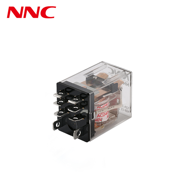
Aging devices require systematic, measurable checks. Coil resistance testing provides a strong diagnostic baseline. You measure coil resistance against data sheet parameters. A significant drop in resistance suggests partial coil shorts. An increase points to wire degradation or terminal oxidation. Use a precision multimeter for these checks.
Contact voltage drop analysis remains highly effective. You measure the millivolt drop across closed contacts under active load. This represents the most reliable indicator of contact health. A high voltage drop means severe carbon build-up exists. You can track this reading over months to predict eventual failure. A healthy PCB power relay shows a stable, low voltage drop.
Establish clear replacement logic for your technicians. Decide when to swap a bad unit versus repairing the surrounding circuit. Sourcing substitute components requires extreme care. Always check pinout compatibility first. Verify footprint alignment precisely. An incompatible replacement damages the entire board.
Troubleshooting Diagnostic Framework
Diagnostic Test | Testing Method | Normal Range | Warning Sign |
|---|---|---|---|
Coil Resistance | Multimeter across coil pins at 20°C | Within ±10% of datasheet | Greater than 15% deviation |
Voltage Drop | Millivolt reading across closed contacts | Under 50mV at 1A load | Steady upward trend over 100mV |
Contact Chatter | Oscilloscope monitoring during turn-on | Under 5 milliseconds | Prolonged bouncing or erratic closure |
Insulation Resistance | Megohmmeter testing at 500VDC | Over 1000 Megohms | Sudden drop below 100 Megohms |
Proper specifications actively reduce your future maintenance burdens. Load matching is an absolute necessity. Utilizing a single coil general purpose power relay requires exact load alignment. Resistive, capacitive, and inductive loads behave very differently. Resistive loads act predictably. Inductive and capacitive loads do not. Mismatched loads cause accelerated contact welding.
Inrush current considerations dictate your initial contact ratings. Transient spikes happen continuously at turn-on. Motors and capacitors draw massive initial surges. These surges can hit ten times the normal running current. You need higher initial ratings to survive these spikes. This holds true even if your steady-state current remains quite low.
You should frame your PCB power relay specifications as preventative maintenance tools. High dielectric strength prevents electrical tracking. It stops short circuits from developing over long-term operation. High isolation between the coil and contacts protects sensitive microcontrollers.
Engineers must apply strict shortlisting logic during design. Prioritize actual operational metrics over raw maximum amperage ratings. Look closely at switching frequency. Evaluate the specific load type thoroughly. Factor in ambient temperature fluctuations. Over-specifying a component sometimes creates issues. A massive 30-amp relay might fail to break a tiny 10-milliamp signal reliably.
Resistive Loads: Heaters and simple lighting. They show minimal inrush current.
Inductive Loads: Motors and solenoids. They create severe arcing upon disconnection.
Capacitive Loads: Power supply filters. They generate massive turn-on current spikes.
Your supply chain directly influences hardware stability. Traceability and manufacturing consistency are vital. Variation across manufacturing lots ruins preventative maintenance schedules. If one batch lasts 100,000 cycles and the next lasts 20,000, predictability vanishes. Highlight the need for strict quality control from the manufacturer.
Credible vendors offer detailed, accessible lifecycle data. A high-quality PCB power relay supplier shares expected electrical life curves openly. They show performance data under varying loads. They do not just publish best-case, resistive-load scenarios. They provide realistic metrics for harsh industrial environments.
Cross-reference capabilities are equally vital for long-term maintenance. Evaluate suppliers based on their legacy support. Excellent suppliers provide drop-in replacements for end-of-life components. Pin-for-pin compatibility is essential. This minimizes redesign costs. It keeps your machines running without requiring major board revisions.
Transparency builds engineering trust. Suppliers should detail their contact materials clearly. They must explain their testing methodologies. Partnering with a reliable vendor acts as an extension of your maintenance department.
Maintenance functions as a holistic process. It spans entirely from initial specification to field troubleshooting. Post-deployment care alone cannot guarantee hardware reliability. You must understand the physics of contact arcing and thermal degradation. You must also implement safe assembly cleaning practices.
The most effective maintenance strategy combines two approaches. You need routine diagnostic testing, specifically focusing on voltage drop and coil resistance. You also need rigorous upfront component evaluation. Never select a component based solely on its maximum current rating.
Engineers and procurement teams should take immediate action. Audit your current relay failure rates today. Consult your supplier’s lifecycle curves for existing components. Review your specification requirements for all upcoming board revisions to ensure perfect load matching.
A: Yes, but it requires careful thermal management. You must operate well below maximum current ratings. You should also select specific coil holding voltages. Dropping the voltage after activation significantly reduces continuous heat generation inside the enclosure.
A: You must know the difference between wash-tight and flux-proof relays. Wash-tight enclosures are fully sealed and withstand aqueous cleaning. Flux-proof units are unsealed. Avoid using aggressive solvents or ultrasonic cleaning on unsealed electromechanical components. Fluid ingress will contaminate the contacts.
A: Look for an increasing voltage drop across closed contacts under load. This reading indicates significant contact degradation. It reveals hidden carbon buildup long before total failure occurs. Replacing the unit at this stage prevents unexpected system downtime.

 注: 建议图片大小150px*50px


