Views: 0 Author: Site Editor Publish Time: 2026-10-07 Origin: Site


Can one microscopic component failure bring an entire industrial control system to a grinding halt? Absolutely. I have seen it happen on the factory floor more times than I care to count. A printed circuit board relay is inherently designed as a reliable electromechanical bridge. However, applying it improperly often leads to catastrophic board failures, melted copper traces, or even severe electrical fires. Integrating high-voltage switching capabilities directly onto low-voltage logic boards is not a task for guesswork. It requires meticulous attention to detail at every single stage of the design cycle.
In this comprehensive guide, we will walk engineers, purchasing managers, and electronics designers through the critical safety rules for deploying these components. From specifying the correct contact materials and maintaining strict electrical isolation to navigating post-assembly cleaning protocols, you will learn how to maximize component lifespan. By the end of this article, you will have the practical engineering knowledge needed to ensure bulletproof product reliability.
Proper Selection is Paramount: Always match contact load characteristics, coil drive voltage, and global safety certifications like UL and VDE to your specific application to prevent premature burnout.
Electrical Isolation Prevents Hazards: Maintaining rigorous creepage and clearance distances shields delicate low-voltage control circuits from lethal high-voltage surges. Optocoupler isolation adds an extra layer of bulletproof protection.
Manage Back EMF Proactively: You must place a flyback diode across the drive coil. This simple addition protects sensitive driving transistors from destructive high-voltage transients when the magnetic field collapses.
Strict Mounting Protocols: Adhere strictly to the manufacturer's soldering temperature profiles and environmental cleaning ratings. Ignoring these will warp internal plastics or contaminate the contacts.
Understand Lifespan Limits: Learn to differentiate between mechanical life, which spans millions of unloaded cycles, and electrical life, which drops to thousands of cycles under full load. Design your system to respect these inherent physical boundaries.
Before diving into specific layout rules, we must look at where the electronics manufacturing industry is heading. The rapid expansion of smart grid technology, electric vehicle charging infrastructure, and industrial IoT devices has fundamentally shifted component requirements. We are currently seeing a massive push toward extreme miniaturization. Engineers are now tasked with packing higher-power switching capabilities into increasingly shrinking board spaces.
This ongoing trend makes thermal management and precise load calculation more critical than ever. Smaller footprints leave absolutely no margin for error regarding heat dissipation. Furthermore, global safety standards are tightening in response to these dense designs. Modern PCB layouts must anticipate harsher environments and higher transient voltage spikes, making robust isolation strategies non-negotiable for regulatory compliance.
At its core, a printed circuit board relay is a compact electromechanical switching device. It is specifically engineered to be soldered directly onto a fiberglass substrate. It acts as an isolated gateway. This gateway allows a low-power digital signal, like a 5V output from a standard microcontroller, to safely command a high-power external load, such as a 240V AC industrial heater.
The operational magic of this component relies on fundamental electromagnetism. When a low-power control voltage is applied to the internal coil, it generates a concentrated magnetic field. This invisible force physically pulls a pivoting metal armature. Because the armature is mechanically linked to a set of conductive contacts, its movement forces the high-power circuit to either snap shut and complete the circuit, or spring open and break the current flow. Once the control signal drops, a tiny mechanical spring instantly snaps the armature back to its resting state.
To fully grasp the safety precautions, one must first visualize the internal anatomy of the switch. The coil generates the magnetic pull, while the armature acts as the moving lever. The contacts carry the heavy load current, and the spring provides the reset force. Finally, the protective enclosure shields these delicate moving parts from external debris.
These miniature powerhouses are ubiquitous across modern electronics. You will find them quietly clicking away inside smart home thermostats, regulating heavy machinery in programmable logic controllers, and managing critical power distribution in automotive electronics.
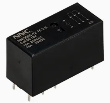
Safety does not begin at the soldering station. It starts weeks earlier during the component specification phase. Selecting an undersized or inappropriate switch for a specific load profile is the leading root cause of catastrophic field failures.
Specifying a component based solely on its steady-state current rating is a dangerous oversight. Engineers must calculate the required contact rating based on the specific transient behavior of the load. Resistive loads, like heating elements, draw a predictable and steady current. In stark contrast, inductive loads like pump motors and capacitive loads like LED power supplies generate massive instantaneous inrush currents. A compressor motor might pull up to ten times its nominal operating current during the first few milliseconds of startup.
If the chosen contacts are only rated for the running current, this violent inrush will quickly melt the standard silver alloy, welding the contacts permanently shut. When dealing with these high-stress environments, selecting a robust PCB relay equipped with Silver Tin Oxide contacts, specifically AgSnO2, provides significantly higher resistance to inrush welding compared to standard Silver Nickel.
Equally critical is providing the exact nominal coil voltage. Common parameters dictate using clean 5V, 12V, or 24V DC supplies. Supplying a voltage lower than the required pick-up threshold yields a weak magnetic field, causing the contacts to chatter, arc, and eventually degrade. Conversely, overdriving the coil with excessive voltage forces it to dissipate abnormal amounts of heat, melting the internal wire insulation and triggering a dead short.
To simplify the engineering process, use the following matrix to match your load type with the appropriate safety considerations.
Load Type | Common Examples | Inrush Current Multiplier | Engineering Recommendation |
|---|---|---|---|
Resistive | Heaters, Incandescent Bulbs | 1x to 1.2x Nominal | Standard AgNi contacts are sufficient. Match rating to steady state. |
Inductive | Motors, Transformers, Solenoids | 5x to 10x Nominal | Select AgSnO2 contacts. Derate the relay by at least 40 percent. |
Capacitive | LED Drivers, Switching Power Supplies | 20x to 40x Nominal | Require specialized high-inrush models. Implement zero-cross switching if possible. |
Procurement teams and hardware designers must rigorously verify that the selected component carries legitimate safety certifications. Marks such as UL, VDE, CE, and RoHS are not just marketing badges. They prove the component has survived brutal independent testing for dielectric strength and flammability. Integrating uncertified gray-market components exposes the final product to regulatory failure and catastrophic liability in the event of a fire.
Mixing 240V mains power with 3.3V logic signals on the same fiberglass substrate introduces severe electrical risks. Robust layout practices are non-negotiable to protect both the end-user and the expensive silicon components.
The physical separation between the dangerous load side and the safe control side is governed by two vital metrics. Clearance is defined as the shortest path through the air between two conductive parts, preventing sudden electrical arcing from lightning strikes or power surges. Creepage, however, is the shortest distance along the surface of the board itself. It prevents tracking, a deadly phenomenon where ambient moisture and dust create a microscopic conductive bridge across the board.
Designers must consult safety standards like IEC 62368-1 to determine the exact millimeter distances required for their specific voltage and environmental pollution degree. A common and highly effective practice is to mill a physical slot completely through the board between the coil and contact pins. This artificially extends the creepage distance and guarantees safety.
When the microcontroller stops sending power to the coil, the collapsing internal magnetic field behaves violently. It generates a massive reverse voltage spike known as Back Electromotive Force. This energy can easily hit hundreds of volts in a matter of microseconds. Left unchecked, this spike will instantly blow out the driving transistor.
To neutralize this threat, a flyback diode must be placed in parallel with the coil, reverse-biased during normal operation. The moment the coil de-energizes, this diode provides a safe, low-resistance loop for the induced current to dissipate harmlessly as heat. This simple addition clamps the voltage spike and saves your logic circuit.
Even the most perfectly specified electromagnetic relays can be destroyed on the assembly line. Because they contain delicate moving parts, they require careful handling during manufacturing.
The external terminal pins are rigidly anchored to the microscopic copper wires of the internal coil. Bending these terminals any closer than 3mm to the plastic base is strictly forbidden. Applying lateral force to the pins during manual insertion can crack the epoxy seal, allowing humidity to penetrate the casing. In extreme cases, mechanical stress will snap the internal coil wire entirely, rendering the component dead on arrival.
These components are constructed using precision-molded plastic bobbins and nylon structural elements that are highly sensitive to thermal shock. Adhering to the manufacturer's specific soldering temperature profile is mandatory. During wave soldering, the peak solder bath temperature must generally be capped at 260 degrees Celsius for no longer than 3 to 5 seconds. Prolonged heat exposure will melt the internal bobbin, permanently warp the contact alignment, or destroy the temper of the return spring.
After assembly, boards are frequently washed to remove corrosive flux residues. However, not all components can survive a chemical bath. Unsealed flux-tight models, known as RT II, are designed only to prevent flux vapors from entering the bottom during soldering. They are absolutely not waterproof. Washing an RT II unit will force liquid solvents directly into the mechanical chamber, coating the contacts in non-conductive residue. If your contract manufacturer utilizes automated washing processes, you must specify a fully encapsulated wash-tight model, known as RT III.
Understanding how to extract the maximum operational life from your components requires a deep dive into datasheet metrics and environmental variables.
Datasheets often boast impressive lifespan figures, but these require careful interpretation. Mechanical life refers to the sheer physical durability of the spring and armature without any electricity flowing through the contacts, often exceeding 10 million cycles. However, electrical life is the metric that actually matters for engineers. It represents the number of cycles the device can endure while switching its maximum rated load.
Because electrical arcing vaporizes a tiny amount of metal every time the contacts open, electrical life is drastically shorter. It is typically rated around 100,000 cycles for a standard 16A 250VAC load. Always base your warranty and maintenance schedules on the electrical life parameter.
Operating a switch in extreme ambient temperatures actively alters the electrical resistance of the copper coil. As heat rises, resistance increases, meaning the coil draws less current at the same voltage. This can result in a magnetic field too weak to pull the armature. High humidity and dust ingress are also fatal to exposed silver contacts, causing rapid oxidation and dangerous localized heating. In harsh industrial settings, deploying a fully sealed RT III model is the only way to guarantee long-term stability.
To engineer a truly robust system, one must objectively acknowledge the physical limitations of electromechanical switches and design around them.
Because they rely on physical mass moving through space, these devices suffer from inevitable wear and tear. Furthermore, they exhibit a bounce time, which is a brief period of a few milliseconds where the contacts physically bounce against each other before settling into a solid connection. Due to this mechanical inertia, they are entirely useless for high-frequency applications like Pulse Width Modulation used in LED dimming or precise motor speed control.
If the inherent limitations of a mechanical switch pose an unacceptable risk to your system, it is time to evaluate a Solid State Relay. Unlike their mechanical cousins, these devices use semiconductor materials like Thyristors or MOSFETs to switch the load. They feature zero moving parts, offering a virtually infinite lifespan, microsecond switching speeds, and completely silent operation. While they are notably more expensive and require dedicated heat sinks to manage thermal output, their performance in high-frequency applications is unmatched.
Even with meticulous design precautions, prototypes fail, and field returns happen. Diagnosing these failures requires a logical, step-by-step approach to identify the root cause and implement lasting corrections.
If your system's load remains permanently powered even after the control signal is turned off, the contacts have likely welded shut. This catastrophic failure mode is almost always caused by unexpected inrush currents that exceed the thermal limits of the contact material, melting the silver alloy into a solid block. To troubleshoot and prevent this, engineers should integrate snubber circuits, which is a precise resistor and capacitor network, in parallel with the load. The snubber absorbs the high-voltage transient during the break phase, suppressing the plasma arc.
If the device fails to emit its characteristic click when commanded, the internal coil has likely burned out. This is typically the result of continuous overvoltage or operating in an environment that exceeds the thermal insulation class of the wire. Grab a digital multimeter and measure the resistance across the coil pins. A reading of infinite resistance confirms that the internal wire has overheated, melted, and snapped open. Ensuring your drive circuit provides a clean, regulated DC voltage is the best defense against coil degradation.
The safe and reliable deployment of switching components requires a holistic, systems-level approach. It demands accurate load profiling, strict adherence to electrical isolation standards, and a deep respect for the physical limitations of electromechanical parts. By carefully managing thermal profiles during soldering, protecting against environmental contamination, and actively mitigating electrical transients like Back EMF, engineers can prevent early device failure in the field.
Respecting these engineering boundaries not only ensures the long-term reliability of your product but also guarantees the fundamental safety of the end-user. Do not leave your board's reliability to chance. For industrial-grade applications requiring uncompromised safety, choosing the right manufacturing partner is just as important as your circuit design. We highly recommend exploring the extensive catalog at NNC Relay. Whether you need high-inrush miniature power relays for smart appliances or fully sealed models for harsh environments, you can find the exact specifications to match your demanding load profiles. Upgrade your component sourcing today to secure the ideal switching solution for your next groundbreaking design.
A PCB relay is specifically engineered for direct integration onto a printed circuit board. It features rigid, compact terminal pins designed for either through-hole or surface-mount automated soldering. These components prioritize miniaturization to fit tight electronic enclosures. In contrast, general-purpose relays are typically bulkier, designed for panel mounting, DIN rails, or plug-in sockets. They are built to handle heavier industrial loads and allow for rapid, tool-less replacement in control cabinets without the need for desoldering.
Testing for safety requires a rigorous, multi-step electrical verification process. First, use a digital multimeter to verify coil continuity and ensure the resistance matches the datasheet. Second, measure the contact resistance while the relay is energized using a four-wire Kelvin method to detect any dangerous internal oxidation. Finally, perform a Dielectric Voltage-Withstand test by applying a high voltage, such as 2000V, between the low-voltage coil pins and the high-voltage contact pins. This ensures the internal isolation barriers are intact and will protect the control circuitry from fatal surges.
You can only wash a unit if it is explicitly rated by the manufacturer as Wash-tight or Fully Sealed. These specific models feature a robust epoxy seal that prevents liquids from penetrating the housing. If the component is rated as Flux-proof or Unsealed, washing it is strictly prohibited. Liquid cleaning agents and dissolved flux will seep into the mechanical chamber, coat the electrical contacts in a non-conductive residue, and cause immediate switching failure once the board dries.
An audible clicking sound confirms that your low-voltage control circuit is successfully powering the coil and moving the internal armature. If electricity is not flowing to the load, the issue lies entirely with the contact surfaces. The contacts may be heavily oxidized from environmental exposure, coated in carbon soot from previous electrical arcing, or contaminated by manufacturing chemicals. Alternatively, if you are switching a very small low-current signal, the voltage might simply be too low to punch through the natural silver-oxide layer on the contacts, requiring a switch to gold-plated contacts instead.
Protecting your control circuit from voltage spikes requires proactive suppression at the source. The most effective method is installing a flyback diode directly across the DC coil terminals, oriented in reverse bias. When the magnetic field collapses, this diode provides a safe path for the induced current to dissipate. For the AC load side, integrating an RC snubber circuit across the contacts will absorb transient energy and significantly reduce destructive arcing during the break phase.
Overheating is typically the result of either coil over-voltage or excessive contact resistance. Supplying a drive voltage higher than the nominal rating forces the coil to dissipate excess power as heat. On the load side, if the contacts are pitted from heavy arcing or carrying a current beyond their maximum rating, the localized resistance increases dramatically. This generates severe thermal stress that can eventually melt the plastic enclosure and lead to total board failure.

 注: 建议图片大小150px*50px


