Views: 124 Author: Site Editor Publish Time: 2026-09-14 Origin: Site


Modern automotive electrical systems carry immense power, pushing every internal switch to its absolute limits. Specifying the wrong automotive relay sets the stage for catastrophic circuit failures. Expensive vehicle recalls often trace back to a single overlooked internal contact. Countless relays look completely identical from the outside, hidden inside standardized black plastic cubes. However, their internal build quality and thermal management capabilities dictate their true lifecycle performance. Ignoring these hidden details compromises critical vehicle safety systems and risks substantial financial loss.
You need a transparent framework to evaluate and shortlist these components properly. We created this guide to provide engineers, procurement managers, and advanced technicians with exactly that. You will learn how to dissect technical datasheets, assess contact materials, and navigate environmental durability testing. Ultimately, you will discover how to make highly confident architectural decisions for your next automotive project.
Comparing relays requires looking beyond basic voltage ratings to evaluate contact material, coil resistance, and thermal thresholds.
Application dictates architecture: switching between standard electromechanical and solid-state relays depends strictly on load type and switching frequency.
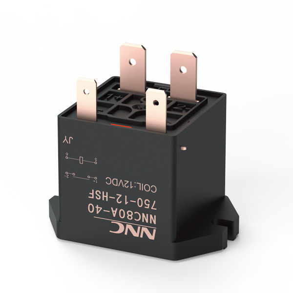
High-demand circuits require specialized components (like the high surge voltage resistant relay nnc80a) to mitigate transient spikes.
Selecting the right automotive relay supplier relies on auditing their compliance (ISO/IATF standards) and batch-testing transparency.
Engineers must evaluate the exact load type before specifying any component. You must differentiate clearly between resistive loads and inductive loads. Resistive loads include simple circuits like cab heaters or incandescent dashboard lights. Inductive loads control complex devices like wiper motors, fuel solenoids, and magnetic clutches. Inductive loads present unique engineering challenges. When you interrupt an inductive circuit suddenly, the collapsing magnetic field generates massive inductive kickback. This stored energy causes violent contact arcing across the gap. Repeated arcing accelerates premature degradation and eventually welds the internal contacts together.
Next, evaluate coil voltage alongside power consumption. You need to identify the critical thresholds for pull-in (operate) voltage and drop-out (release) voltage. A system might supply 12V nominally, but heavy battery drops during cold engine cranking reduce this significantly. You must ensure the pull-in voltage remains low enough to activate reliably under severe electrical strain. Engineers face a strict trade-off here. Low coil power consumption saves battery life but produces weaker internal magnetic fields. Weaker magnetic fields result in lower contact pressure, dramatically increasing electrical resistance.
Finally, contact material selection directly impacts electrical longevity. You cannot treat all silver alloy contacts equally. We frequently compare Silver Tin Oxide (AgSnO2) against Silver Nickel (AgNi). Use AgNi for stable, continuous loads where consistent low-resistance switching matters most. Conversely, specify AgSnO2 for high inrush currents. AgSnO2 resists contact welding exceptionally well during aggressive motor starts or high-capacitance lighting loads. Matching these specific contact materials to their optimal use cases prevents premature failures.
Best Practice: Always attach an oscilloscope across the load during bench testing. This reveals the true peak of your inductive kickback. You cannot calculate this accurately on paper alone.
Common Mistake: Engineers frequently specify AgNi contacts for heavy blower motors. The high inrush current quickly welds the AgNi contacts. You must use AgSnO2 for these aggressive start-up applications.
Contact Material | Primary Strength | Ideal Automotive Application | Vulnerability |
|---|---|---|---|
Silver Nickel (AgNi) | Low, stable contact resistance | Continuous resistive loads, sensors | Prone to welding under high inrush |
Silver Tin Oxide (AgSnO2) | High resistance to contact welding | Motors, lamps, capacitive loads | Slightly higher initial contact resistance |
Silver Copper (AgCu) | Excellent thermal conductivity | Basic signaling, low-cost circuits | Oxidizes quickly in harsh environments |
Vehicles operate in chaotic electrical environments. You must protect sensitive downstream electronic control units (ECUs) from sudden voltage spikes. Alternator spikes and load dumps happen frequently in real-world driving. A load dump occurs when a battery disconnects suddenly while the alternator charges heavily. This violent event sends massive voltage transients surging through the vehicle wiring harness. Standard switches cannot survive these extreme events without sustaining severe internal damage.
You must deploy specialty surge-resistant models for aggressive environments. Electric vehicles and heavy-duty commercial trucks demand highly robust architectures. To handle these extremes, you should specify benchmark components. For example, the high surge voltage resistant relay nnc80a excels at handling extreme transient voltages. Robust components absorb sudden shocks effortlessly, keeping expensive downstream modules perfectly safe. They form a critical defense layer in high-demand EV and commercial applications.
Furthermore, you need to evaluate internal protection mechanisms. Many engineers integrate parallel resistors or flyback diodes directly within the relay housing. A parallel resistor absorbs excess coil energy during de-energization. This absorbs and suppresses voltage transients effectively. Alternatively, a flyback diode provides a safe, low-resistance path for inductive kickback current. While diodes offer superior suppression capabilities, they make the component strictly polarity-sensitive. You must wire them correctly during assembly.
Best Practice: Position transient suppression devices as close to the source of the spike as physically possible. This minimizes the length of wire acting as an antenna for electromagnetic interference (EMI).
Common Mistake: Technicians often install diode-suppressed relays backward. Reversing the coil polarity forces massive current straight through the forward-biased diode. It vaporizes the diode instantly, destroying the component permanently.
Thermal management dictates true reliability in the field. Under-the-hood temperatures routinely exceed 125°C. You cannot rely strictly on room-temperature datasheets for automotive design. Engineers must learn how to read a manufacturer's derating curve carefully. This specific curve illustrates how maximum load capacity drops safely as ambient temperature rises. If you ignore the derating curve entirely, you risk catastrophic thermal runaway. Excessive heat increases internal contact resistance. Higher resistance generates more heat, eventually melting the entire plastic housing.
Ingress protection and vibration resistance also determine component survival. You must define exactly when to use unsealed, dust-proof, or hermetically sealed components. Unsealed units work fine inside climate-controlled interior cabins. Dust-proof models protect against airborne debris but fail under direct moisture exposure. Epoxy-sealed hermetic relays survive harsh engine bays and exposed chassis mounts. Prolonged mechanical vibration in automotive environments destroys weak components quickly. Harmonic resonance shakes internal tension springs, causing unwanted contact bouncing. This rapid bouncing creates intense micro-arcs, degrading the silver contact plating rapidly.
Finally, demand absolute lifecycle testing transparency from your manufacturing partners. You must understand the vast difference between mechanical life expectancy and electrical life expectancy. Mechanical life often reaches one million cycles easily. This inflated number only proves the spring and armature move freely without an electrical load. However, electrical life expectancy under full load looks very different. Electrical life often drops closer to one hundred thousand cycles. You must base your procurement decisions exclusively on the electrical lifecycle data. Always test components under your specific load conditions to verify real-world durability.
Best Practice: Mount components with their terminal pins pointing downward whenever possible. This simple physical orientation prevents gravity from pulling condensation or leaked engine fluids into the housing seams.
Common Mistake: Procurement teams frequently mistake basic "dust-cover" enclosures for fully "sealed" enclosures. Placing a dust-cover unit inside a humid engine bay guarantees rapid internal corrosion and premature failure.
Choosing between Electromechanical Relays (EMR) and Solid-State Relays (SSR) represents a major architectural decision. You must weigh the fundamental pros and cons objectively.
Electromechanical Relays remain the dominant industry standard for most automotive systems. They offer exceptionally high tolerance for severe overvoltage situations. Field technicians appreciate the audible clicking sound, confirming operation during manual troubleshooting. They also boast a significantly lower upfront procurement cost. However, EMRs suffer from unavoidable mechanical wear over time. Contact bouncing remains a constant physical limitation. They also deliver much slower switching speeds compared to digital alternatives.
Solid-State Relays provide a modern alternative designed for high-frequency switching. They offer an infinite operational lifespan because they contain absolutely no moving parts. SSRs provide totally silent operation and achieve remarkable microsecond switching times. These specific traits make them perfect for precise pulse-width modulation (PWM) tasks like variable-speed fan controllers. However, SSRs remain highly vulnerable to high-voltage transients. They generate significant thermal waste during operation, requiring bulky external heat sinks. Furthermore, they carry a much higher initial procurement cost per unit.
You need a rapid logic system to make the right choice based on project constraints. Follow these critical steps to finalize your architecture:
Determine your precise switching frequency requirements (PWM requires SSR).
Evaluate your maximum ambient temperature constraints and heat sink space.
Assess your system's overall tolerance for mechanical failure over time.
Calculate your available budget for both the component and necessary thermal management hardware.
Evaluation Criteria | Electromechanical Relay (EMR) | Solid-State Relay (SSR) |
|---|---|---|
Switching Speed | Slow (Milliseconds) | Extremely Fast (Microseconds) |
Operational Lifespan | Limited by mechanical wear | Virtually infinite (no moving parts) |
Transient Voltage Tolerance | High (Can absorb minor spikes) | Low (Requires strict circuit protection) |
Acoustic Noise | Audible click (Useful for diagnostics) | Completely silent |
Thermal Management Needs | Low (Self-contained) | High (Requires dedicated heat sinks) |
Identifying the perfect component means little if your partner cannot deliver it reliably. You must learn how to vet a highly dependable automotive relay supplier thoroughly. Start by auditing their core manufacturing certifications. You should mandate the supplier holds active IATF 16949 and ISO 9001 certifications. These specific credentials ensure they follow rigorous automotive-grade quality control protocols globally. Without an IATF 16949 certification, you cannot trust their assembly line consistency.
Next, evaluate their traceability and testing protocols deeply. A trustworthy manufacturing partner provides comprehensive datasheets for every component they sell. You should evaluate their willingness to share RoHS compliance data openly. Furthermore, demand custom batch-testing results before accepting large bulk shipments. Transparent suppliers will happily share destructive testing reports and thermal analysis data. If a vendor hesitates to provide raw engineering test data, you should walk away immediately.
Finally, assess their long-term supply chain resilience. Global component shortages can paralyze vehicle production lines instantly. You must assess their standard shipping lead times carefully. Clarify their minimum order quantities (MOQs) to ensure they align perfectly with your production scale. A strong partner also demonstrates the unique ability to provide drop-in replacements for legacy footprint components. This flexibility protects your assembly line when primary brands fail to deliver parts on time.
Best Practice: Request independent third-party lab verification for ISO and IATF certificates. Do not rely blindly on a static PDF downloaded from a vendor website.
Common Mistake: Buyers often lock themselves into proprietary footprint designs to save upfront PCB tooling costs. This traps you with a single vendor indefinitely. Always design your boards to accept standard ISO footprint layouts.
Successful component comparison relies entirely on matching your exact automotive relay specifications to the circuit's physical and electrical realities. You cannot simply swap one black box for another based on voltage alone. We strongly encourage you to document your exact load requirements immediately. Calculate your maximum operating temperatures accurately using proper derating curves. Map out all potential inductive kickback threats in your schematic. Once you define these exact parameters, request engineering samples and detailed datasheets from a fully vetted manufacturing partner. Test these samples rigorously under full electrical loads before committing to any bulk procurement. Taking these precise, data-driven action steps ensures you deploy a highly reliable, durable electrical architecture.
A: A 4-pin model operates as a Single Pole Single Throw (SPST) switch. It simply turns a single circuit completely on or off. A 5-pin model functions as a Single Pole Double Throw (SPDT) switch. It actively toggles power between two different circuits. When the coil rests, power flows to one default pin. When energized, power flips instantly to the secondary pin.
A: Burning typically traces back to undersized wire gauges causing severe terminal heating. You might also be utilizing a switch with insufficient continuous current ratings. Failing to account for massive high inrush currents on heavy motor loads will melt internal contacts rapidly. Always calculate peak transient loads carefully, never just the nominal running currents.
A: No. Standard models only feature basic plastic dust covers to repel large debris. True "weatherproof" or fully sealed models carry an IP67 rating, utilizing specialized internal epoxy potting. Standard unsealed units will corrode rapidly and fail completely if exposed to direct moisture, heavy engine bay washdowns, or total submersion.

 注: 建议图片大小150px*50px


