Views: 157 Author: Site Editor Publish Time: 2026-09-01 Origin: Site


Engineers and system designers rely heavily on automated switching components to build reliable circuits. Choosing the wrong switch often turns a functional prototype into a frustrating maintenance nightmare.
Incorrect relay selection leads directly to contact welding, coil burnout, and costly system downtime. At the decision stage, moving from a general design concept to a specific component requires absolute precision. You must match exact electrical, mechanical, and environmental parameters to your application.
This guide provides a definitive framework for evaluating load types, coil requirements, and lifecycle factors. You will learn how to specify the correct component for industrial, commercial, or logic-level applications. By following these steps, you can confidently navigate datasheets and prevent catastrophic field failures.
Evaluate the load first: Inductive and capacitive loads require significantly higher contact ratings than resistive loads.
Match coil specifications to the controller: Ensure your control circuit (e.g., PLC or microcontroller) can safely drive the relay coil's voltage and current.
Prioritize isolation and maintenance: Features like lockable test buttons reduce downtime in industrial panels.
Vet your supply chain: A reliable electromagnetic relay supplier is as critical as the component's datasheet, especially for long-term scalability and compliance.
Selecting the core switching technology determines how your circuit behaves under stress. A common business problem arises when engineers over-specify a Solid State Relay (SSR) when a standard electromagnetic relay is perfectly sufficient. Conversely, using mechanical switches in high-frequency applications guarantees premature failure.
Mechanical switches offer distinct advantages across multiple engineering domains. Let us examine the core reasons you might choose them over solid-state alternatives.
True Galvanic Isolation: Mechanical switches provide a physical air gap. They completely disconnect the circuit when resting. This complete physical disconnection is highly critical for safety compliance in high-voltage power systems.
Cost-Efficiency: They require a significantly lower upfront cost, especially for multi-pole configurations. Complex logic circuits need multiple paths, and mechanical options handle this cheaply.
Heat Dissipation: Mechanical contacts generate minimal heat while closed. SSRs drop voltage across their semiconductor junctions, which generates substantial heat. Mechanical options eliminate the need for bulky, expensive heat sinks inside control panels.
Mechanical parts inherently feature a finite mechanical lifespan. Moving parts wear out over time. If your specific application requires switching faster than 10 to 20 milliseconds, you face a major risk. Similarly, switching millions of cycles per month destroys mechanical springs and contacts rapidly. In these high-speed scenarios, you must pivot to an SSR.
Table 1: High-Level Technology Comparison
Feature | Mechanical Option (EMR) | Solid State Option (SSR) |
|---|---|---|
Physical Air Gap | Yes (True Galvanic Isolation) | No (Leakage current exists) |
Switching Speed | Slow (10-20 ms) | Extremely Fast (< 1 ms) |
Heat Generation | Very Low | High (Requires heat sinks) |
Lifespan | Finite (Mechanical wear) | Virtually Unlimited |
Engineers must separate the evaluation process into two completely isolated circuits. You have the Control (or Coil) side and the Load (or Contact) side. Merging these in your mind causes severe specification errors. Analyzing accurate electromagnetic relay specifications prevents these expensive mistakes.
The input side dictates how you trigger the switch. Your controller must provide enough energy to create a magnetic field.
Nominal Voltage & Pick-up/Drop-out Voltage: You must ensure the control logic reliably triggers the coil. Microcontrollers typically output 5V or 12V DC. Industrial Programmable Logic Controllers (PLCs) often use 24V DC or 120V AC. The pick-up voltage represents the minimum threshold required to close the contacts. The drop-out voltage is the threshold where contacts release. Environmental temperature fluctuations shift these thresholds, so read datasheets carefully.
Coil Power Consumption: Always calculate the exact current draw. A direct drive from delicate microcontrollers like an Arduino or Raspberry Pi frequently overloads the board. A standard board pin supplies around 20mA, while a coil might demand 70mA. You must use an intermediary transistor, relay module, or optocoupler to protect your logic board.
The output side manages the actual heavy lifting. It connects or disconnects the main power source from the target device.
Contact Capacity (Amps/Volts): Never strictly match the continuous load listed on a spec sheet. A 10-amp load needs more than a 10-amp switch. Always apply a 1.5x to 2x safety margin. This buffer protects your circuit during unexpected power fluctuations.
Contact Form: Determine the exact required switching logic. Use Single Pole Single Throw (SPST) for simple on/off tasks. Use Double Pole Double Throw (DPDT) when you need to reverse motor direction or switch two separate circuits simultaneously.
Load Type Derating: All loads behave differently upon startup. A 10A resistive load rating absolutely does not equal a 10A inductive load rating. Motors and transformers represent inductive loads. They pull massive inrush currents upon startup. You must apply heavy derating to inductive loads to prevent the contacts from fusing together.
Failing to account for temperature rises inside sealed enclosures, which increases coil resistance.
Assuming a generic AC rating perfectly translates to a DC rating. DC loads sustain damaging arcs much longer than AC loads.
The physical design dictates your installation speed, maintenance efficiency, and spatial footprint. Scalability and the surrounding environment heavily influence this choice.
Industrial settings demand rapid troubleshooting and robust physical connections. Downtime costs factories thousands of dollars per minute.
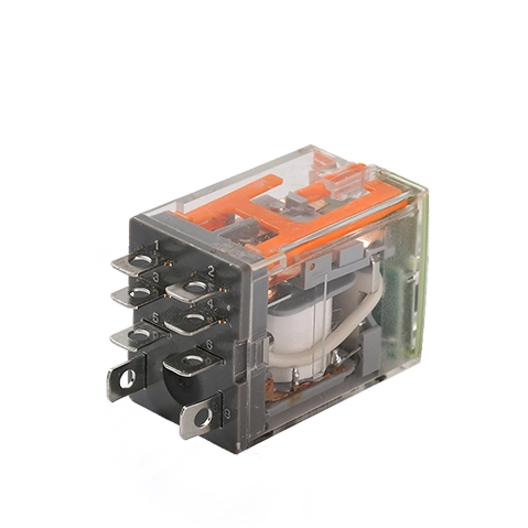
Automation panels typically require DIN-rail compatible sockets. Sockets allow technicians to execute rapid replacements without desoldering wires. When building control panels, always specify a miniature electromagnetic relay with lockable test feature. A lockable test button allows technicians to manually actuate the switch without applying coil voltage. This manual override greatly accelerates diagnostic workflows. Technicians can visually verify load responses safely during routine panel inspections.
Printed Circuit Board (PCB) applications present completely different constraints. Space remains the most critical premium.
PCB designs require low-profile, through-hole, or Surface Mount Device (SMD) packages. You must carefully calculate vertical clearances if stacking multiple boards. Furthermore, these components must feature sealed, wash-tight enclosures if the PCB will undergo automated washing processes. Conformal coating used to protect boards from moisture easily seeps into unsealed switches, completely ruining the internal mechanical contacts.
Measure your panel depth before ordering DIN-rail sockets. Some socket combinations protrude too far for standard enclosures.
Always check the pin pitch (the distance between pins) against your PCB layout software to avoid routing conflicts.
Specify gold-plated contacts if you plan to switch extremely low-current audio or logic signals, as standard silver oxidizes and blocks micro-currents.
Datasheets often present best-case scenarios. Real-world applications rapidly degrade mechanical components if designers ignore electrical physics.
A datasheet may proudly claim a mechanical life of 10,000,000 cycles. However, do not base your maintenance schedule on this number. The electrical life under full load might only reach 100,000 cycles. Mechanical life only measures how long the spring and armature move without any electrical current passing through them. Base your Return on Investment (ROI) calculations strictly on the electrical life rated for your specific load type.
High DC voltages cause severe problems when contacts open. Unlike AC, DC voltage never crosses zero. Consequently, DC power sustains violent electrical arcs as the physical air gap widens. This arcing vaporizes contact material and creates carbon buildup. If you switch high-voltage DC, evaluate whether you need models containing magnetic blowout features. Magnetic blowouts use internal magnets to pull the electrical arc away from the contacts, extinguishing it quickly.
When you de-energize a coil, the collapsing magnetic field generates a massive high-voltage spike. This spike shoots backward into the control circuit. This reverse voltage easily destroys transistors and microcontrollers. You must ensure your design incorporates inductive kickback protection. Use flyback diodes placed in reverse parallel across DC coils. For AC coils, implement varistors or RC snubber circuits. These simple additions safely dissipate the destructive energy spike.
Choosing a vendor involves far more than simply finding the lowest price. It represents a critical risk-management decision. A poorly manufactured batch can compromise your entire product line.
First, examine their compliance and certification history. You must firmly reject suppliers lacking verifiable UL, CSA, VDE, or TUV markings. Fake or missing certifications open your company to massive liability. The components must meet local electrical safety codes to ensure consumer safety and industrial compliance.
Ask prospective vendors for their Mean Time Between Failures (MTBF) data. Request recent batch-testing documentation. An ISO 9001 certified electromagnetic relay supplier implements stringent quality control checks. They monitor contact resistance variances across production runs. Consistent contact resistance guarantees reliable thermal performance in the field.
Never commit to bulk procurement based solely on a PDF datasheet. Request detailed engineering specification sheets first. Next, order engineering samples. Install these samples into your physical prototype. Measure the actual thermal performance under load. Verify the precise coil current draw using an oscilloscope. Only after physical validation should you finalize your procurement contract.
Selecting the right switching component requires balancing delicate control-side constraints against harsh load-side realities. You must prioritize generous physical safety margins to accommodate unpredictable inrush currents. Always remember to separate your mechanical life expectations from actual electrical life limitations. Incorporate critical safety additions like flyback diodes and lockable test buttons to protect both the circuitry and the maintenance technicians.
To move forward, consult detailed engineering datasheets to finalize your load calculations. Do not hesitate to contact technical sales representatives for custom sample requests. They provide application-specific derating guidance tailored precisely to your operational environment.
A: AC coils include a shading ring on the magnetic core. This ring prevents the relay from chattering or buzzing as the alternating current crosses zero. A DC coil fed with AC will chatter violently. Conversely, an AC coil fed with DC will likely draw excessive current, overheat, and burn out quickly.
A: Contact welding occurs due to massive inrush currents from capacitive or motor loads, or from severe arcing. Prevent it by over-sizing the contact amperage rating. You can also use zero-cross switching logic or select specialized, highly robust contact materials like Silver Tin Oxide (AgSnO2).
A: No. Microcontrollers output 3.3V or 5V at very low current, typically under 20mA. You must use a relay module containing a driver transistor. Alternatively, you can use an intermediary optocoupler combined with a separate 24V power supply to safely trigger the industrial coil.

 注: 建议图片大小150px*50px


