Views: 112 Author: Site Editor Publish Time: 2026-10-19 Origin: Site


Engineers design solid state relays for high-frequency, long-lifespan switching. These components should theoretically last forever. However, premature performance degradation often causes unexpected system downtime and expensive maintenance delays.
Unlike mechanical relays, SSRs never suffer from contact wear. Their internal degradation occurs for completely different reasons. Performance loss is almost exclusively tied to thermal mismanagement, transient electrical stresses, and specification mismatches. Many systems fail simply because designers misunderstand these unseen forces.
This guide equips technical buyers and engineers with a practical diagnostic framework. You will learn how to identify the root causes of SSR degradation. We will also explore how to evaluate datasheets accurately and choose the correct components for reliable deployment.
Continuous voltage drop across the relay generates heat; inadequate thermal dissipation is the primary cause of premature failure.
Unmitigated transient spikes from inductive loads (like motors) can exceed internal semiconductor tolerances (dv/dt ratings).
Protecting an SSR requires specialized ultra-fast fuses (I²t ratings), as standard breakers will not react quickly enough to prevent short-circuit damage.
Evaluating accurate solid state relay specifications based on real-world operating temperatures—not just ideal laboratory maximums—is critical for long-term reliability.
Heat kills semiconductors. Understanding thermal dynamics is your first defense against premature failure.
Every solid state device possesses an inherent forward voltage drop. When conducting electricity, the internal thyristor or transistor resists the flow slightly. This voltage drop typically hovers between 1.0 and 1.5 volts. It might seem negligible, but it creates significant thermal energy during continuous operation.
Continuous current directly translates to localized heating. You calculate this heat generation using a simple formula: Watts = Amps × Voltage Drop. If your application pushes 20 amps through a relay having a 1.5V drop, the device generates 30 watts of pure heat. This thermal energy builds up rapidly inside a small plastic and metal enclosure. You must remove this heat efficiently. Otherwise, the internal semiconductor junction will overheat.
Proper heat dissipation relies on mechanical coupling. Failing to extract heat is a frequent engineering oversight. Common heat sinking failures include:
Improperly sized heat sinks: Selecting a sink based solely on physical footprint rather than thermal resistance ratings.
Poor thermal compound application: Using too much or too little thermal paste traps air. Air is a terrible thermal conductor.
Restricted ambient airflow: Placing relays inside sealed cabinets prevents convective cooling. Heat simply recirculates around the components.
Ignoring thermal stress leads directly to thermal runaway. As the semiconductor junction temperature rises, its internal resistance characteristics change. The device begins generating even more heat. Eventually, excessive junction temperature permanently alters the semiconductor properties. The silicon structure degrades. This leads to an inability to turn off, known as latching. In extreme cases, the component undergoes complete physical breakdown.
Resistive loads behave predictably. Inductive loads, however, introduce harsh electrical transients. You must account for these forces when integrating a solid state relay into your system.
Motors, solenoids, and transformers store energy in magnetic fields. When the relay switches off, the magnetic field suddenly collapses. This collapse generates a massive back-EMF (Electromotive Force). The resulting voltage spike travels backward into the relay. These transient overvoltage events routinely exceed normal operating limits.
Semiconductors possess specific dv/dt limits. This metric defines the maximum allowable change in voltage over time. When an inductive load creates a fast, violent voltage spike, the rapid change can trigger unintended switching. The relay might briefly turn back on. Repeatedly exceeding dv/dt limits will eventually punch through the semiconductor isolation, ruining the device.
You must mitigate transient overvoltage proactively. Engineers deploy two primary defense mechanisms:
RC Snubber Circuits: Many premium relays include internal RC (Resistor-Capacitor) snubbers. These circuits absorb the rapid voltage changes, protecting the thyristor.
Transient Voltage Suppressors (TVS): External Metal Oxide Varistors (MOVs) clamp excess voltage. They shunt destructive spikes away from the sensitive relay junctions.
You must evaluate your specific application environment to determine which mitigation strategy fits best.
Consider a 1 HP 120VAC motor. Under normal running conditions, it draws a steady current. However, starting a resting motor requires massive rotational force. This start-up phase demands up to six times the steady-state current. You cannot use a relay rated strictly for the running current. You must over-spec the relay to handle this severe transient demand safely.
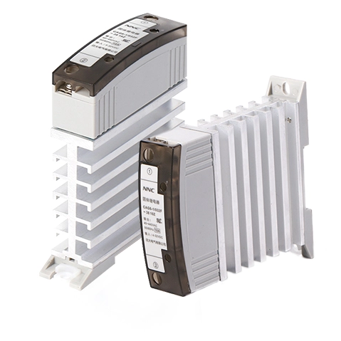
Transient electrical events destroy relays faster than thermal degradation. Protecting against current surges requires specialized knowledge.
You must differentiate between nominal operating current and allowable transient surge current. A relay might confidently carry 25 amps indefinitely. The same device might survive a 250-amp spike, provided it only lasts for one alternating current cycle (typically 16.6 milliseconds). Exceeding this exact time-current threshold will vaporize internal wire bonds.
Some loads deceive standard calculations. Tungsten lamps and certain heating elements exhibit "cold resistance." When sitting at room temperature, their electrical resistance is remarkably low. Energizing them causes a massive initial current spike. As the element heats up, its resistance rises, and the current drops to a normal level. You must calculate this initial surge to avoid overloading the semiconductor components.
Datasheets provide an I²t rating. This value defines the maximum thermal energy the relay can absorb during a short-circuit before physical destruction occurs. It represents current squared multiplied by time. This specific metric exists solely to guide your fusing decisions.
Standard mechanical circuit breakers fail to protect semiconductors. Mechanical breakers rely on physical bimetallic strips or magnetic coils. They take milliseconds or even full seconds to physically trip. By the time a mechanical breaker opens the circuit, the semiconductor has already vaporized. You must use specialized ultra-fast acting semiconductor fuses. These fuses match the I²t rating of the relay, clearing faults instantly to prevent component destruction.
Laboratory specifications rarely reflect factory floor realities. You must interpret data through the lens of actual deployment conditions.
Every datasheet features a thermal derating curve. This graph is your most important design tool. Relays never operate at their maximum current rating in hot environments. Typically, derating begins at 40°C. If ambient cabinet temperatures reach 60°C, a 50-amp relay might safely conduct only 25 amps. Ignoring this curve guarantees premature equipment failure.
Physical constraints dictate relay selection. Panel mount configurations offer massive surface area for heat sinks. They excel in high-current applications. Conversely, high speed din rail solid state configurations optimize cabinet space. They allow for rapid installation. However, packing multiple DIN rail units tightly restricts airflow. You must map out heat dissipation pathways carefully.
Electrical anomalies on the load side must never reach your control logic. Proper input/output isolation is mandatory. Look for optical isolation specifications. An internal LED sends a light beam to a photoreceiver across an air gap. This physical separation provides excellent dielectric strength, shielding sensitive microcontrollers from high-voltage disasters.
Matching the switching type to the load prevents erratic behavior. Analyzing solid state relay specifications requires understanding when the device actually turns on.
Switching Type Comparison Chart
Switching Type | Ideal Load Application | Key Benefit | Common Use Case |
|---|---|---|---|
Zero-Cross | Resistive loads (heaters) | Minimizes EMI and surge currents | Industrial baking ovens |
Random Turn-On | Inductive loads (motors) | Immediate response, avoids phase delays | Phase-angle dimming, solenoids |
Zero-cross relays wait for the AC sine wave to hit zero volts before engaging. This minimizes electromagnetic interference (EMI). Random turn-on relays engage the exact millisecond they receive a control signal. They handle inductive loads better because they avoid lagging phase issues.
Sourcing unreliable components creates massive procurement risks. You must evaluate the manufacturing partner just as rigorously as the component.
Reputable suppliers provide comprehensive engineering data. They do not hide behind vague marketing terms. Look for detailed derating curves, precise thermal resistance data (measured in °C/W), and proven MTBF (Mean Time Between Failures) metrics. If a supplier lacks this documentation, their products pose a severe integration risk.
Industrial components must meet strict safety guidelines. Verify all compliance markings. UL, CSA, and CE certifications ensure the component satisfies rigorous industrial safety and environmental standards. Independent testing prevents catastrophic electrical fires and liability issues.
Engineering assistance matters deeply. Complex applications require nuanced thermal calculations and detailed load profiling. A superior solid state relay supplier offers direct access to applications engineers. They help you run thermal simulations and verify fuse coordination before you finalize the design.
Supply chain stability prevents production line halts. Assess the manufacturer's batch testing protocols. Do they test every unit under load? Clear warranty terms also reduce procurement risk. Consistent quality assurance guarantees your deployed systems perform reliably year after year.
SSR performance loss is highly predictable and preventable through accurate load profiling and thermal design.
Prioritize datasheets that reflect your actual enclosure temperatures and transient conditions. Never design based solely on laboratory maximums.
Always implement ultra-fast semiconductor fuses and properly sized heat sinks to protect your investments.
Consult with engineering support to review specific load characteristics before finalizing bulk procurement or system integration.
A: Overvoltage spikes or extreme thermal stress physically melt the internal silicon junction. Once the semiconductor material melts, it fuses together. This permanently shorts the connection, forcing the relay to stay securely locked in the "on" position regardless of control inputs.
A: Standard multimeters are insufficient because all SSRs naturally exhibit minor leakage current when off. You must test the relay under an active load. Measure the forward voltage drop across the output terminals while energized. A significant deviation from the datasheet value indicates severe internal degradation.
A: Yes. Internal thyristors require a specific holding current to remain latched on. Furthermore, inherent leakage current can keep highly sensitive, low-power loads (like LEDs or small PLCs) partially energized even when the relay switches off. You must match specifications carefully.

 注: 建议图片大小150px*50px


