Views: 0 Author: Site Editor Publish Time: 2026-06-28 Origin: Site


Control panel real estate is incredibly expensive today. Furthermore, component thermal failures remain costly. Transitioning to solid-state technology requires precision component selection. Unlike older electromechanical relays, solid-state relays (SSRs) offer infinite lifespans. They also deliver rapid switching capabilities. However, they introduce critical thermal management challenges. You must handle heat effectively to prevent unexpected system shutdowns. Selecting the right DIN-rail solid state relay requires careful balancing. You must weigh load requirements against panel space constraints. You also need to understand thermal derating realities thoroughly. Proper evaluation ensures long-term, fail-safe operation. Engineers often underestimate these operational parameters. This oversight easily leads to premature component degradation. We will explore how to analyze your load type accurately. You will also learn to interpret derating curves correctly. Finally, we will outline protective features necessary for modern control panels. You can then confidently specify reliable components for your next automation project.
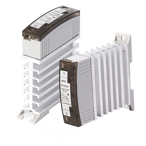
DIN-rail SSRs streamline panel wiring and save space via integrated heatsinks, lowering installation labor compared to traditional panel mount SSRs.
Accurate selection hinges on matching the SSR to the specific load profile (resistive vs. inductive) and understanding inrush current risks.
Thermal derating is non-negotiable; an SSR’s maximum current rating drops significantly as the ambient temperature inside the control panel rises.
Integrated protective features (snubber circuits, overvoltage protection) are critical for high-speed switching environments.
Traditional control panels often suffer from severe spatial crowding. Engineers frequently struggle to fit multiple components into standard enclosures. This challenge multiplies when using standard panel mount SSR units. These older designs demand separate heatsinks. Installers must carefully apply thermal paste to ensure proper heat transfer. They also have to drill holes and tap threads into the backplate. These manual steps dramatically inflate installation labor times. Every additional minute spent mounting components hurts the project budget.
Modern DIN-rail relays solve these integration hurdles seamlessly. They combine the actual switching element and an optimized heatsink. Manufacturers package both into a single, modular unit. This unified design eliminates the messy thermal paste application. It also removes the need for custom backplate machining. You simply align the relay and snap it onto a standard 35mm rail. This plug-and-play approach revolutionizes control panel assembly.
Switching to a rail-mounted architecture delivers immediate benefits. First, it significantly reduces installation time. Snap-on mounting replaces tedious drilling and tapping procedures. Second, it standardizes panel layouts perfectly. Modular components create clean, organized wiring pathways. Finally, it drastically lowers future maintenance efforts. Solid-state technology eliminates moving mechanical parts entirely. You no longer worry about worn contacts or arcing failures. The entire system becomes vastly more reliable over its operational lifespan.
Specifying an industrial solid state relay requires a methodical approach. You cannot simply read the baseline amperage on a datasheet. You must evaluate the load behavior, voltage limits, and switching dynamics.
Your load type dictates the fundamental switching method required. Misinterpreting this causes immediate operational failures.
Resistive Loads (Heaters): Industrial heater bands and curing ovens act as purely resistive loads. These applications require standard zero-crossing relays. The relay waits until the AC voltage sine wave crosses zero before actuating. This synchronized timing prevents electrical noise and extends component life.
Inductive Loads (Motors, Transformers): Solenoids, transformers, and electric motors behave differently. They create significant phase shifts between voltage and current. Inductive loads demand random turn-on relays. These relays actuate instantly upon receiving the control signal. They effectively manage the phase discrepancies inherent in inductive circuits.
Load Characteristic | Recommended SSR Type | Primary Application Example | Switching Behavior |
|---|---|---|---|
Pure Resistive | Zero-Crossing | Industrial Heaters | Actuates at 0V point on AC curve |
Highly Inductive | Random Turn-On | Motors & Transformers | Actuates instantly on command |
Nominal ratings on relay packaging are often deceptive. A relay rated for 20 Amps is rarely meant to run continuously at 20 Amps. You should always size the relay for 120% to 150% of your continuous operating current. This buffer accounts for unexpected line fluctuations. It also prevents premature thermal degradation. Furthermore, you must analyze maximum blocking voltage requirements. A 240V AC line can experience transient spikes much higher than nominal limits. Selecting a relay rated for a 600V minimum blocking voltage prevents unwanted misfires.
Some automation processes require incredibly precise temperature regulation. These scenarios often employ PID loop controllers. In these setups, you must evaluate the necessity of a high-speed SSR. High-speed models provide rapid actuation for accurate dosing or heating. However, this speed comes with trade-offs. Higher switching speeds increase the risk of generating electromagnetic interference (EMI). You might need to install external line filters to mitigate this electrical noise.
Engineers must respect the physics of solid-state switching. Unlike mechanical contacts, silicon components possess internal resistance. Relays generate approximately 1 to 1.2 watts of pure heat per ampere of load current. Switching a 40-amp load continuously generates nearly 48 watts of thermal energy. Inside a sealed metal enclosure, this heat accumulates rapidly. Without proper dissipation, the silicon die will quickly exceed its safe operating limits and fail.
Manufacturer datasheets always include thermal derating curves. Understanding these charts is critical for your panel's survival. A relay advertised as a "40A" unit rarely handles 40 Amps in a real industrial setting. If the internal panel temperature reaches 50°C (122°F), that same relay might only handle 20 Amps safely. You must evaluate manufacturer thermal derating charts strictly based on the ambient temperature inside the enclosure. Never use the external room temperature for your calculations.
Integrated heatsinks only function correctly if air can circulate around them. You must highlight the necessity of minimum vertical and horizontal spacing. Placing DIN-rail components tightly against each other creates stagnant heat pools. Always follow the manufacturer's recommended clearance metrics.
Best Practices for Relay Placement
Leave a minimum of 20mm horizontal clearance between adjacent switching modules.
Ensure at least 40mm of vertical clearance above and below the device.
Avoid placing relays directly above heat-producing transformers or power supplies.
Mandate forced-air cooling (using exhaust fans) when natural convection cannot keep the internal ambient temperature below 40°C.
Steady-state current calculations only tell half the story. Motor startups and incandescent lamp loads act aggressively when initially powered. They can easily draw 7 to 10 times their normal steady-state current for several milliseconds. This massive surge can instantly vaporize the internal thyristor. You must ensure the relay's surge current rating exceeds the maximum possible fault current. Engineers measure this capability using the $I^2t$ specification. An adequate $I^2t$ buffer guarantees the relay survives brutal startup spikes.
Inductive loads generate aggressive electrical kickback when deactivated. The magnetic field collapses and shoots a high-voltage spike back down the line. To survive this, you should specify a protective SSR. These advanced units feature built-in Transient Voltage Suppressors (TVS). Many also utilize robust Metal Oxide Varistors (MOVs) across their output terminals. These internal components absorb the destructive voltage spikes safely. They prevent the silicon switch from conducting erratically during transient events.
Even the best relays cannot survive a direct short circuit without external help. Standard mechanical circuit breakers act too slowly to protect solid-state components. The silicon die will fracture long before a mechanical breaker trips. You must integrate fast-acting semiconductor fuses into your panel design. Class T or Class J fuses react in a fraction of a millisecond. They successfully interrupt the fault current before thermal destruction occurs inside the relay.
Navigating vendor catalogs can overwhelm even experienced panel builders. Follow this systematic shortlisting logic to secure the exact DIN rail SSR for your application.
Step 1: Define the baseline limits. You must calculate your exact steady-state current first. Next, determine your maximum potential inrush current. Finally, model or measure the expected maximum internal panel temperature during summer operating conditions.
Step 2: Compare form factors. Evaluate the physical width of the available units. Some ultra-slim designs measure just 17.5mm wide. Others require a broader 22.5mm footprint. Compare these dimensions against your available rail track space.
Step 3: Verify Compliance and Quality. Never purchase unverified switching components. Shortlist vendors who provide proven UL, CSA, and CE certifications. You should immediately reject any components lacking published, verifiable derating curves.
Step 4: Assess Connection Types. Vendors offer various termination styles. Choose between standard screw terminals, spring-cage, or modern push-in connections. Base this decision on the panel builder's specific vibration resistance requirements. Spring-cage terminals often excel in high-vibration manufacturing environments.
Specifying a rail-mounted solid-state relay is fundamentally an exercise in risk mitigation. Success heavily depends on strictly adhering to thermal limits and load characteristics. You cannot simply shop by reading a baseline amperage rating on a box. To guarantee long-term reliability, keep the following action items in mind:
Map your exact load profile, identifying whether it behaves resistively or inductively.
Calculate your enclosure's maximum internal ambient temperature to apply derating curves accurately.
Size your relay components at 120% to 150% of the normal continuous operating current.
Implement fast-acting semiconductor fuses to protect against sudden short circuits.
Instruct your engineering teams and buyers to gather all environmental data first. They must map their exact load parameters before ever requesting vendor datasheets or evaluation samples.
A: The main differences are form factor and thermal management. DIN rail models usually feature pre-integrated heatsinks and snap directly onto standard 35mm rails. Conversely, panel mount versions require flat surface mounting, separate external heatsinks, and careful thermal compound application.
A: No, most are sold as complete "contactors" with integral heatsinks included. However, their maximum current rating is completely dependent on this built-in cooling capability. This dependency is exactly why reading manufacturer derating charts remains critical.
A: Overheating is typically caused by inadequate panel ventilation or insufficient horizontal spacing between adjacent modules. It also frequently occurs when engineers fail to derate the relay appropriately for high ambient enclosure temperatures.
A: It turns on only when the AC voltage sine wave crosses the zero point. This synchronized switching minimizes aggressive surge currents and reduces electrical noise. It is ideal for pure resistive loads like industrial heating elements.

 注: 建议图片大小150px*50px


