Views: 136 Author: Site Editor Publish Time: 2026-02-21 Origin: Site


Micro switches, also known as snap-action switches, are small but powerful components in various electronic and industrial applications. Their main function is to provide precise and reliable switching in devices where accuracy and speed are crucial. Whether you need them for household appliances, automotive systems, or industrial machinery, wiring a micro switch correctly ensures its longevity and reliable performance. In this detailed guide, we will walk you through everything you need to know about how to wire a micro switch, from the basics to step-by-step instructions, wiring configurations, troubleshooting, and best practices.
Before diving into the process of wiring a micro switch, it’s important to understand what a micro switch is and how it functions. A micro switch is an electromechanical device that uses a physical force to activate an electrical circuit. The "micro" in the name refers to the minimal mechanical movement required to trigger the switch.
A micro switch is a type of switch that operates with minimal physical force. It’s designed to switch a circuit on or off with a quick snap action, which is highly reliable and efficient. The internal mechanism typically uses a spring-loaded actuator, which snaps the switch between open and closed positions.
A micro switch is composed of several parts that work together to enable reliable switching:
Actuator: The movable part that is pressed, pulled, or triggered to initiate the switch.
Contacts: The electrical parts that open or close the circuit when the actuator is engaged.
Housing: The outer casing that protects the internal components.
Spring: A spring inside the switch that ensures the actuator returns to its original position after being triggered.
There are different types of micro switches designed for specific applications. Below is a summary of common types:
Type | Description | Best Used For |
Basic Micro Switch | Standard micro switch with a lever actuator. It provides reliable snap-action switching for general purposes. | General-purpose applications such as household appliances. |
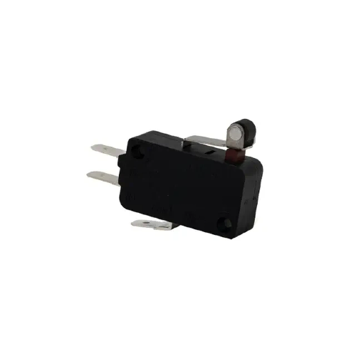
Roller Micro Switch | Features a roller on the actuator for smoother operation, reducing wear and tear. | Applications with repetitive movements like conveyor belts. |
Subminiature Micro Switch | A compact version of the standard micro switch. Perfect for applications with limited space. | Consumer electronics and small equipment. |
Sealed Micro Switch | Designed to be resistant to water, dust, and other environmental factors. | Harsh environments such as outdoor machinery or industrial sites. |
High-Current Micro Switch | Capable of handling higher currents compared to standard micro switches. | High-power applications like automotive and heavy machinery. |
Before wiring a micro switch, you’ll need a few essential tools and an understanding of the switch’s terminals. Let's walk through the components and tools required for wiring.
To wire a micro switch, you'll need the following tools:
Wire Strippers: For stripping the insulation from the ends of the wires.
Screwdriver: For tightening screws on the switch terminals.
Soldering Iron: If necessary, for making a permanent connection to the terminals.
Multimeter: To check for continuity and verify correct wiring.
Appropriate Wires: The correct wire gauge for your application.
A micro switch typically has three terminals: Common (C), Normally Open (NO), and Normally Closed (NC). Understanding these terminals is crucial for proper wiring:
Common (C): This terminal is the central connection point where the power enters or exits the switch.
Normally Open (NO): The NO terminal is open by default and will only make contact when the switch is actuated.
Normally Closed (NC): The NC terminal is closed by default and will open when the switch is triggered.
Each terminal plays a crucial role in determining the behavior of the switch when it is activated.
Wiring a micro switch correctly ensures that it functions as expected and performs reliably over time. Below is a step-by-step guide to help you wire a micro switch.
Start by stripping the ends of the wires that you will be connecting to the micro switch terminals. Use wire strippers to remove the insulation carefully, exposing about 1/4 inch of the wire. Ensure that the wires are of the correct gauge for the switch's rating to avoid overloading the switch.
Determine which terminal you will use based on the configuration required for your application:
For a Normally Open (NO) configuration, connect the power wire to the Common (C) terminal and the load wire to the NO terminal.
For a Normally Closed (NC) configuration, connect the power wire to the Common (C) terminal and the load wire to the NC terminal.
Using a screwdriver or a soldering iron (if necessary), connect the prepared wires to the appropriate terminals. Tighten the screws to secure the wires in place. Ensure that there is no loose connection, as this can result in unreliable operation of the switch.
Once the micro switch is wired, it’s important to test it before use. Using a multimeter, check for continuity between the Common (C) terminal and either the NO or NC terminal, depending on the configuration:
NO: There should be no continuity until the switch is triggered.
NC: Continuity should be present until the switch is triggered.
Test the wiring by manually activating the switch and ensuring that it behaves as expected.
Micro switches are versatile and can be wired in different configurations depending on the application. Let's explore some common wiring configurations for different uses.
In a Normally Open (NO) configuration, the switch is open by default, and it only closes the circuit when it is triggered. This is the most commonly used configuration for controlling devices that should only be activated when a specific condition is met.
Safety Interlocks: Used in machines to ensure that safety guards are in place before the machine can operate.
Limit Switches: In conveyors, to detect the position of moving parts.
In a Normally Closed (NC) configuration, the switch is closed by default, allowing current to flow through the circuit until the switch is triggered, which opens the circuit. This setup is used when a device needs to be powered unless there is an emergency or safety condition that interrupts the flow.
Emergency Stop Buttons: In industrial settings where pressing the button should immediately cut off power to a system.
Alarm Systems: To detect when a door or window is opened.
Sometimes, despite following the correct wiring procedure, issues can still arise. Below are some common problems and how to troubleshoot them.
If the wires aren’t connecting properly to the micro switch terminals, check for the following:
Loose screws: Ensure that the screws are tightened securely around the wire ends.
Wire insulation: Ensure that no insulation is left on the part of the wire that needs to make contact with the terminal.
Wrong wire gauge: Verify that the wire gauge is appropriate for the switch’s current rating.
If the micro switch doesn’t activate or deactivate as expected, check:
Incorrect terminal connection: Ensure that the correct terminals are used for NO or NC configurations.
Faulty switch: If the switch still doesn’t work after testing, it may be damaged or defective.
Use a multimeter to check for continuity and verify the correct wiring. This will help you identify any issues before using the switch in a live circuit.
To ensure that your micro switches perform reliably over time, follow these best practices when wiring them:
Always disconnect power before wiring a micro switch to avoid electrical shock or damage.
Use insulated tools to reduce the risk of accidental short circuits.
Ensure that each wire is securely attached to the terminals to avoid poor contact and unreliable performance.
For permanent connections, consider soldering the wires rather than using screws.
Use the correct wire gauge and ensure that the current rating of the micro switch matches the application’s requirements to prevent overheating or failure.
Wiring a micro switch correctly is essential for ensuring reliable performance and longevity. By following the steps outlined in this guide, you can confidently wire a micro switch for your specific application, whether it’s for industrial automation, household appliances, or automotive systems. It's important to test your wiring before installation and adhere to best practices for secure and safe connections to avoid potential issues. Proper wiring ensures that your micro switch will operate accurately and efficiently over time, preventing costly downtime and repairs.
At Clion Electric Co., Ltd., we specialize in providing high-quality micro switches designed to meet the needs of various industries. Our products are built to ensure long-lasting, reliable performance in a wide range of applications. If you're looking for expert guidance or the perfect micro switch solution for your project, we invite you to reach out to us. Our team is here to help you select the right components and ensure the success of your wiring projects. Let us assist you in making the best choice for your switching needs.
NO terminals are open by default and only close when triggered. NC terminals are closed by default and open when triggered.
Micro switches are typically designed for low voltage control, but certain models can handle higher currents. Ensure the switch is rated for the voltage and current in your system.
Not necessarily. Most micro switches have screw terminals that don’t require soldering. However, some applications may require soldering for a more permanent connection.
Use a multimeter to check for continuity in the desired positions (NO or NC) to verify the switch is operating correctly when actuated.
Incorrect wiring can lead to malfunctioning switches, failure to trigger, or even damage to the device or circuit. Always double-check connections and configurations before powering up.

 注: 建议图片大小150px*50px


